D-Link DES 6000 Product Manual - Page 16
IDENTIFYING EXTERNAL COMPONENTS, Front Panel, Side Panels
 |
UPC - 790069239328
View all D-Link DES 6000 manuals
Add to My Manuals
Save this manual to your list of manuals |
Page 16 highlights
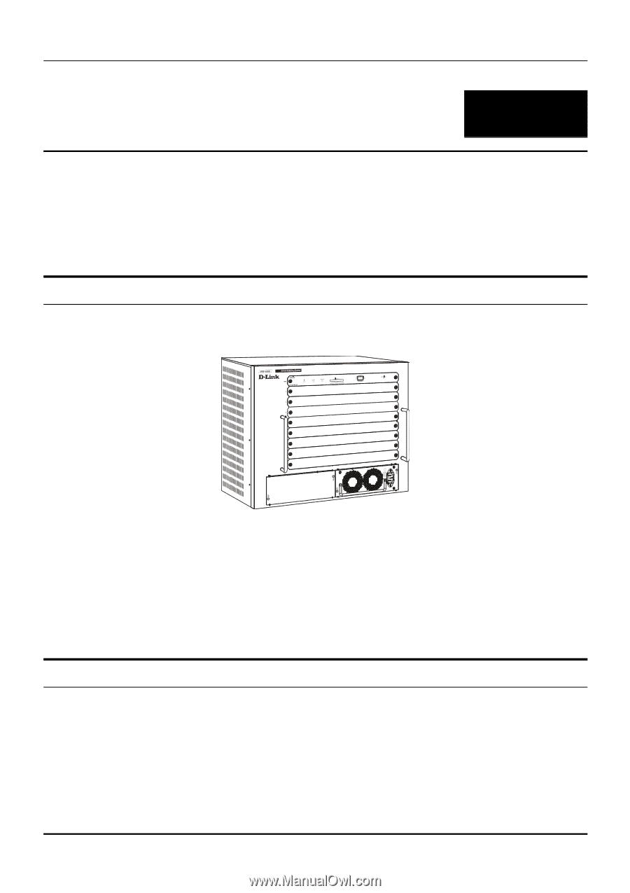
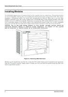
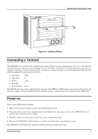
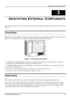
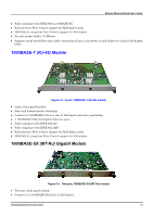
Modular Ethernet Switch User's Guide 3 IDENTIFYING EXTERNAL COMPONENTS This chapter describes the front panel, side panels, optional plug-in modules, and LED indicators of the Switch Front Panel The front panel of the Switch consists nine slide-in module slots for networking modules, two slide-in module slots for power supply modules, an RS-232 communication port, and LED indicators. Figure 3-1. Front panel view of the Switch ♦ Comprehensive LED indicators display the conditions of the Switch and status of the network. A description of these LED indicators follows (see LED Indicators). ♦ An RS-232 DCE console port is used to diagnose the Switch via a connection to a terminal (or PC) and Local Console Management. ♦ Nine slide-in module slots installing networking modules and the CPU module. ♦ Two slide-in module slots for installing power supply modules. Side Panels The left side panel of the Switch contains four system fans. The right side panel contains heat vents. The system fans are used to dissipate heat. The sides of the system also provide heat vents to serve the same purpose. Do not block these openings, and leave adequate space at the rear and sides of the Switch for proper ventilation. Be reminded that without proper heat dissipation and air circulation, system components might overheat, which could lead to system failure. Identifying External Components 11
-
 1
1 -
2
-
3
-
4
-
5
-
6
-
7
-
8
-
9
-
10
-
 11
11 -
 12
12 -
 13
13 -
 14
14 -
 15
15 -
 16
16 -
 17
17 -
 18
18 -
 19
19 -
 20
20 -
 21
21 -
22
-
23
-
24
-
25
-
26
-
27
-
28
-
29
-
30
-
31
-
32
-
33
-
34
-
35
-
36
-
37
-
38
-
39
-
40
-
41
-
42
-
43
-
44
-
45
-
46
-
47
-
48
-
49
-
50
-
51
-
52
-
53
-
54
-
55
-
56
-
57
-
58
-
59
-
60
-
61
-
62
-
63
-
64
-
65
-
66
-
67
-
68
-
69
-
70
-
71
-
72
-
73
-
74
-
75
-
76
-
77
-
78
-
79
-
80
-
81
-
82
-
83
-
84
-
85
-
86
-
87
-
88
-
89
-
90
-
91
-
92
-
93
-
94
-
95
-
96
-
97
-
98
-
99
-
100
-
101
-
102
-
103
-
104
-
105
-
106
-
107
-
108
-
109
-
110
-
111
-
112
-
113
-
114
-
115
-
116
-
117
-
118
-
119
-
120
-
121
-
122
-
123
-
124
-
125
-
126
-
127
-
128
-
129
-
130
-
131
-
132
-
133
-
134
-
135
-
136
-
137
-
138
-
139
 |
 |