D-Link DGS-1016TG User Guide - Page 11
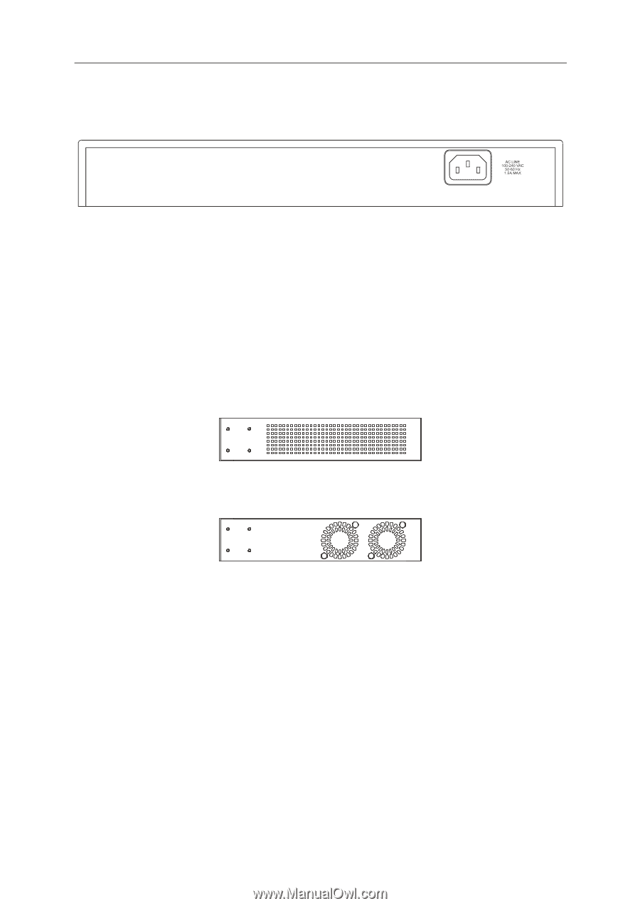
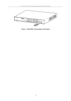
Rear Panel Description, Gigabit Combo Ports, Rear panel view of the Switch
 |
UPC - 790069262142
View all D-Link DGS-1016TG manuals
Add to My Manuals
Save this manual to your list of manuals |
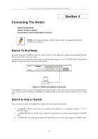
Page 11 highlights
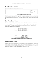
D-Link DGS-1016T Unmanaged Gigabit Ethernet Switch Rear Panel Description The rear panel of the switch contains an AC power connector. Figure 1-3. Rear panel view of the Switch The AC power connector is a standard three-pronged connector that supports the power cord. Plug-in the female connector of the provided power cord into this socket, and the male side of the cord into a power outlet. The switch automatically adjusts its power setting to any supply voltage in the range from 100 ~ 240 VAC at 50 ~ 60 Hz. Side Panel Description The right-hand side panel of the Switch contains two system fans. The left-hand side panel contains heat vents. The system fans are used to dissipate heat. The sides of the system also provide heat vents to serve the same purpose. Do not block these openings, and leave at least 6 inches of space at the rear and sides of the switch for proper ventilation. Be reminded that without proper heat dissipation and air circulation, system components might overheat, which could lead to system failure. Figure 1-4. Side Panels (the left-hand panel is pictured on top) Gigabit Combo Ports In addition to the 16 10/100/1000 Mbps ports, the Switch features two Mini GBIC Combo ports. These two ports are 1000BASE-T copper ports (provided) and Mini-GBIC ports (optional). See the diagram below to view the two Mini-GBIC port modules being plugged into the Switch. Please note that although these two front panel modules can be used simultaneously, the ports must be different. For example, if port 15 is used on the Mini GBIC module, port 15 is not available on the 1000BASE-T module, and vice versa. 11
-
 1
1 -
2
-
3
-
4
-
5
-
 6
6 -
 7
7 -
 8
8 -
 9
9 -
 10
10 -
 11
11 -
 12
12 -
 13
13 -
 14
14 -
 15
15 -
 16
16 -
17
-
18
-
19
-
20
-
21
-
22
-
23
-
24
-
25
-
26
-
27
-
28
-
29
-
30
 |
 |