D-Link DGS-1100 User Manual 1.00 WW - Page 7
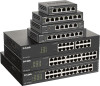
Rear Panel, DGS-1100-08V2, Front Panel, Link/Act/Speed LED Ports 1-8
 |
View all D-Link DGS-1100 manuals
Add to My Manuals
Save this manual to your list of manuals |
Page 7 highlights
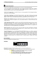
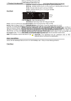
1 Product Introduction D-Link Smart Managed Switch User Manual L'équipement est conçu pour une installation dans un bâtiment et ne doit pas être connecté à des réseaux exposés (installations extérieures), notamment des environnements de campus, et l'ITE doit être connecté uniquement à des réseaux PoE sans acheminement vers une installation extérieure." ou équivalent. CAUTION: This unit is supplied by POE through an UL Listed ITE. Cet appareil est fourni par POE via un ITE répertorié UL. Rear Panel Figure 1.4 - DGS-1100-05PDV2 Rear Panel Power: Use RJ45 to connect the PD port (port 5) and Power over Ethernet Adapter Kit. Kensington Lock: This is used to attach a physical Kensington security lock. GND: This is used to connect the Switch to ground. NOTE: The power budget is 18 Watts with 802.3at and 8 Watts with 802.3af for DGS-1100-05PDV2. DGS-1100-08V2 8-Port 10/100/1000Mbps Smart Managed Switch. Front Panel Figure 1.5 - DGS-1100-08V2 Front Panel Power LED: The Power LED lights up when the Switch is connected to a power source. Link/Act/Speed LED (Ports 1-8): 10/100/1000 Mbps ports to connect Ethernet devices to the switch. CAUTION: The equipment power supply cord shall be connected to a socket-outlet with earthing connection. Le cordon d'alimentation de l'équipement doit être branché sur une prise de courant dotée d'une connexion à la terre. Rear Panel Figure 1.6 - DGS-1100-08V2 Rear Panel 4
-
 1
1 -
 2
2 -
 3
3 -
 4
4 -
 5
5 -
 6
6 -
 7
7 -
 8
8 -
 9
9 -
 10
10 -
 11
11 -
 12
12 -
13
-
14
-
15
-
16
-
17
-
18
-
19
-
20
-
21
-
22
-
23
-
24
-
25
-
26
-
27
-
28
-
29
-
30
-
31
-
32
-
33
-
34
-
35
-
36
-
37
-
38
-
39
-
40
-
41
-
42
-
43
-
44
-
45
-
46
-
47
-
48
-
49
-
50
-
51
-
52
-
53
-
54
-
55
-
56
 |
 |
