D-Link DGS-3620-28PC Hardware Installation Guide - Page 12
Front-Panel Components - dgs 28sc
 |
View all D-Link DGS-3620-28PC manuals
Add to My Manuals
Save this manual to your list of manuals |
Page 12 highlights
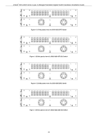
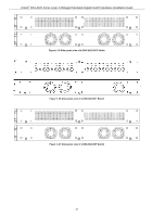
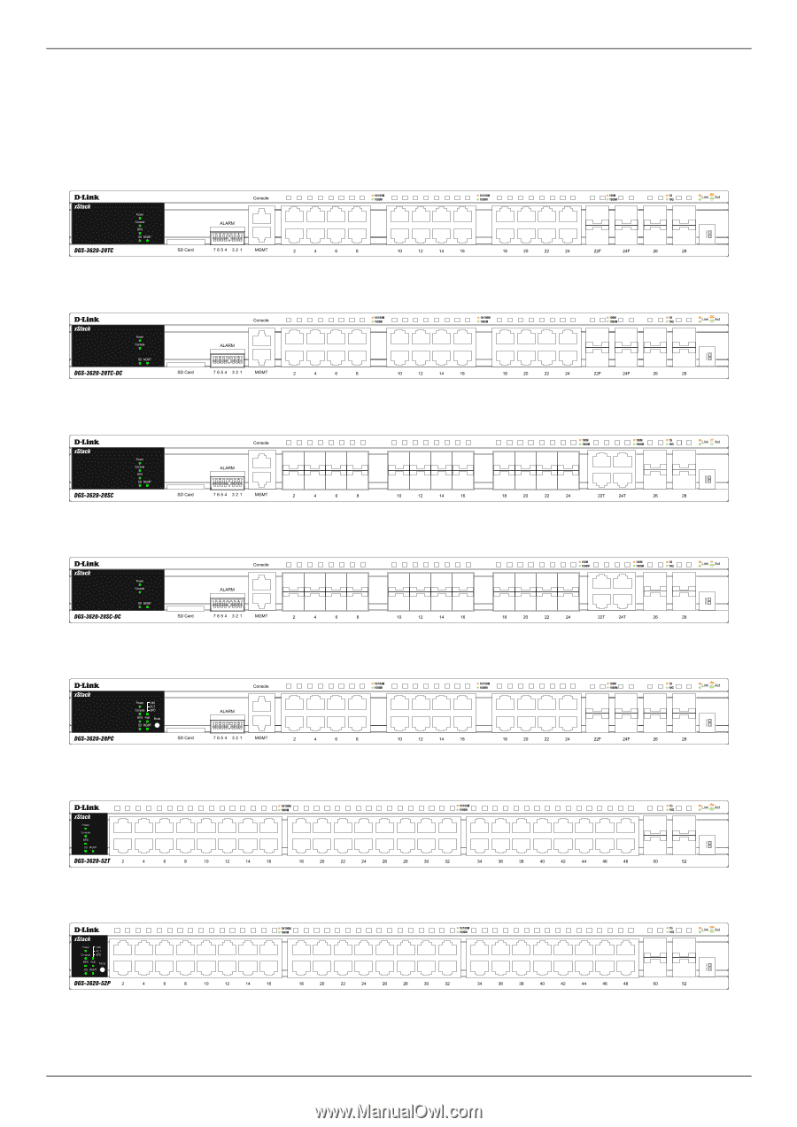
xStack® DGS-3620 Series Layer 3 Managed Stackable Gigabit Switch Hardware Installation Guide Front-Panel Components The front panel of the DGS-3620 Series consists of a Management and Console port, LED indicators for Power, Console, an Alarm Port, and stacking ID LED's. A separate table below describes LED indicators in more detail. Figure 1-1 Front panel view of a DGS-3620-28TC Switch Figure 1-2 Front panel view of a DGS-3620-28TC-DC Switch Figure 1-3 Front panel view of a DGS-3620-28SC Switch Figure 1-4 Front panel view of a DGS-3620-28SC-DC Switch Figure 1-5 Front panel view of a DGS-3620-28PC Switch Figure 1-5 Front panel view of a DGS-3620-52T Switch Figure 1-6 Front panel view of a DGS-3620-52P Switch 12
-
 1
1 -
2
-
3
-
4
-
5
-
6
-
 7
7 -
 8
8 -
 9
9 -
 10
10 -
 11
11 -
 12
12 -
 13
13 -
 14
14 -
 15
15 -
 16
16 -
 17
17 -
18
-
19
-
20
-
21
-
22
-
23
-
24
-
25
-
26
-
27
-
28
-
29
-
30
-
31
-
32
-
33
-
34
-
35
-
36
-
37
-
38
-
39
-
40
-
41
-
42
-
43
-
44
-
45
-
46
-
47
-
48
-
49
-
50
-
51
-
52
-
53
-
54
-
55
-
56
-
57
-
58
-
59
-
60
-
61
-
62
-
63
-
64
-
65
-
66
-
67
-
68
-
69
 |
 |
xStack
®
DGS-3620 Series Layer 3 Managed Stackable Gigabit Switch Hardware Installation Guide
12
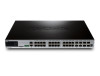
Front-Panel Components
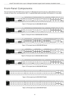
The front panel of the DGS-3620 Series consists of a Management and Console port, LED indicators for Power,
Console, an Alarm Port, and stacking ID LED’s. A separate table below describes LED indicators in more detail.
Figure 1–1 Front panel view of a DGS-3620-28TC Switch
Figure 1–2 Front panel view of a DGS-3620-28TC-DC Switch
Figure 1–3 Front panel view of a DGS-3620-28SC Switch
Figure 1–4 Front panel view of a DGS-3620-28SC-DC Switch
Figure 1–5 Front panel view of a DGS-3620-28PC Switch
Figure 1–5 Front panel view of a DGS-3620-52T Switch
Figure 1–6 Front panel view of a DGS-3620-52P Switch