D-Link DGS-3620-28PC Hardware Installation Guide - Page 18
Installation, Package Contents, Installation Guidelines
 |
View all D-Link DGS-3620-28PC manuals
Add to My Manuals
Save this manual to your list of manuals |
Page 18 highlights
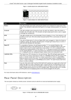
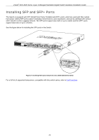
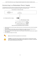
xStack® DGS-3620 Series Layer 3 Managed Stackable Gigabit Switch Hardware Installation Guide Chapter 2 Installation Package Contents Installation Guidelines Power On (AC Power) Alarm Connector Installing SFP and SFP+ Ports Connecting to a Redundant Power Supply External Redundant Power System Package Contents Open the shipping carton of the Switch and carefully unpack its contents. The carton should contain the following items: • One DGS-3620 Series Switch • One AC power cord (this depends on the type of DGS-3620 being shipped). The DC version wouldn't need AC power. • One RJ-45 to RS-232 console cable • One mounting kit (two brackets and screws) • Four rubber feet with adhesive backing • One CD kit for CLI reference guide/Web UI reference guide/Hardware Installation Guide/D-View module If any item is missing or damaged, please contact your local D-Link Reseller for replacement. Installation Guidelines Please follow these guidelines for setting up the Switch: • Install the Switch on a sturdy, level surface that can support at least 6.6 lb. (3kg - This is without PoE functionality) of weight. Do not place heavy objects on the Switch. • The power outlet should be within 1.82 meters (6 feet) of the Switch. • Visually inspect the power cord and see that it is fully secured to the AC power port. • Make sure that there is proper heat dissipation from and adequate ventilation around the Switch. Leave at least 10 cm (4 inches) of space at the front and rear of the Switch for ventilation. • Install the Switch in a fairly cool and dry place for the acceptable temperature and humidity operating ranges. • Install the Switch in a site free from strong electromagnetic field generators (such as motors), vibration, dust, and direct exposure to sunlight. • When installing the Switch on a level surface, attach the rubber feet to the bottom of the device. The rubber feet cushion the Switch, protect the casing from scratches and prevent it from scratching other surfaces. 18
-
 1
1 -
2
-
3
-
4
-
5
-
6
-
7
-
8
-
9
-
10
-
11
-
12
-
 13
13 -
 14
14 -
 15
15 -
 16
16 -
 17
17 -
 18
18 -
 19
19 -
 20
20 -
 21
21 -
 22
22 -
 23
23 -
24
-
25
-
26
-
27
-
28
-
29
-
30
-
31
-
32
-
33
-
34
-
35
-
36
-
37
-
38
-
39
-
40
-
41
-
42
-
43
-
44
-
45
-
46
-
47
-
48
-
49
-
50
-
51
-
52
-
53
-
54
-
55
-
56
-
57
-
58
-
59
-
60
-
61
-
62
-
63
-
64
-
65
-
66
-
67
-
68
-
69
 |
 |