D-Link DGS-3620-28PC Hardware Installation Guide - Page 21
Alarm Connector Port, Contact, Description, Output. Normal Closed Pin. 42VAC or 60VDC
 |
View all D-Link DGS-3620-28PC manuals
Add to My Manuals
Save this manual to your list of manuals |
Page 21 highlights
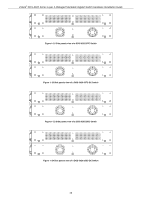
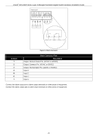
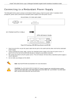
xStack® DGS-3620 Series Layer 3 Managed Stackable Gigabit Switch Hardware Installation Guide Figure 2-4 Alarm Connector Contact 1 2 3 4 5 6 7 Alarm Connector Port Description Output. Normal Closed Pin. (42VAC or 60VDC) Output. Common Pin. (42VAC or 60VDC) Output. Normal Open Pin. (42VAC or 60VDC) Input 2 Input 2 Input 1 Input 1 Connect the alarm input pins to alarm output terminals on other pieces of equipment. Connect the alarm output pins to alarm input terminals on other pieces of equipment. 21
-
 1
1 -
2
-
3
-
4
-
5
-
6
-
7
-
8
-
9
-
10
-
11
-
12
-
13
-
14
-
15
-
 16
16 -
 17
17 -
 18
18 -
 19
19 -
 20
20 -
 21
21 -
 22
22 -
 23
23 -
 24
24 -
 25
25 -
 26
26 -
27
-
28
-
29
-
30
-
31
-
32
-
33
-
34
-
35
-
36
-
37
-
38
-
39
-
40
-
41
-
42
-
43
-
44
-
45
-
46
-
47
-
48
-
49
-
50
-
51
-
52
-
53
-
54
-
55
-
56
-
57
-
58
-
59
-
60
-
61
-
62
-
63
-
64
-
65
-
66
-
67
-
68
-
69
 |
 |

xStack
®
DGS-3620 Series Layer 3 Managed Stackable Gigabit Switch Hardware Installation Guide
21
Figure 2–4 Alarm Connector
Alarm Connector Port
Contact
Description
1
Output. Normal Closed Pin. (42VAC or 60VDC)
2
Output. Common Pin. (42VAC or 60VDC)
3
Output. Normal Open Pin. (42VAC or 60VDC)
4
Input 2
5
Input 2
6
Input 1
7
Input 1
Connect the alarm input pins to alarm output terminals on other pieces of equipment.
Connect the alarm output pins to alarm input terminals on other pieces of equipment.