D-Link DIS-200G Quick Install Guide - Page 7
Grounding the Switch, Connecting to a Power Source
 |
View all D-Link DIS-200G manuals
Add to My Manuals
Save this manual to your list of manuals |
Page 7 highlights
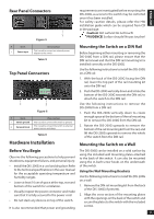
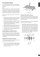
ENGLISH Grounding the Switch To use the DIS-200G safely, it needs to be grounded. Please complete these steps before powering-on the switch. Note: The grounding screw of the chassis must be properly connected to the protective earthing of building in compliance with local regulatory guidelines by using a green-and-yellow grounding cable with the minimum wire gauge 0.75 mm2. Figure 11 Use the following instructions to ground the DIS-200G: 1. Remove the grounding screw from the top of the DIS-200G and place the grounding cable lug ring on top of the grounding screw opening. 2. Insert the grounding screw back into the grounding screw opening and use a screwdriver to tighten the grounding screw, securing the grounding cable to the DIS-200G. 3. Attach the terminal lug ring at the other end of the grounding cable to an appropriate grounding source. 4. Verify that the connection between the grounding connector on the DIS-200G and the grounding source is secure. Connecting to a Power Source The DIS-200G can be powered using a power adapter (optional) or by using the in-built terminal connector. This allows dual power inputs, using wires from the power source(s) screwed-in to the terminal connections. Using the Terminal Connections Before proceeding, ensure that all power sources have been disconnected from the DIS-200G, and that the power source you are wiring to the DIS-200G is also disconnected. Use the following instructions to power the DIS-200G using the terminal connections: 1. Before continuing, consult the diagram below to decide which wires from the power source need to connect to which contacts on the terminal block. Note that two power sources can be used; one inserted into V1-/V1+ (labeled PWR1) and the other inserted into V2-/V2+ (labeled PWR2). If you only wish to use one power source, insert the wires into V1-/V1+ (PWR1). This diagram is also provided on the DIS-200G: Using the Power Adapter (Optional) Use the following instructions to power the DIS-200G using the power adapter (optional): 1. Connect the supplied power adapter to the power connector on the back of the DIS-200G. Connect the other end of the power adapter to a mains power source. Figure 12 5
-
 1
1 -
 2
2 -
 3
3 -
 4
4 -
 5
5 -
 6
6 -
 7
7 -
 8
8 -
 9
9 -
 10
10 -
 11
11 -
 12
12 -
13
-
14
-
15
-
16
 |
 |
