D-Link DSR-250v2 Quick installation guide 2 - Page 5
Initial Configuration
 |
View all D-Link DSR-250v2 manuals
Add to My Manuals
Save this manual to your list of manuals |
Page 5 highlights
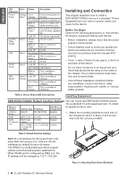
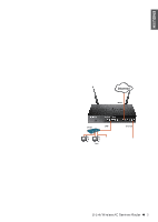
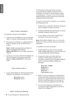
ENGLISH 2. Then, use the screws provided with the equipment rack to mount the device in the rack. Connecting the Device to a Network This section provides basic information about physically connecting the DSR-500AC / 1000AC to a network. To connect the necessary cables as shown in Figure 5. 1. Connect an RJ-45 cable from the port labeled WAN1 to the external router. The port WAN1 is pre-allocated to the WAN1 network segment. 2. Connect an RJ-45 cable from the port labeled LAN (1-4) to a switch in the LAN network segment. 3. Connect an RJ45-to-DB9 cable from the console port for CLI (Command Line Interface) management access. Figure 4. Installing the Wireless AC Services Router in a standard-sized equipment rack Connecting Power and Turning On/Off The AC Power adapter shipped with the device connects the device to earth ground when plugged an AC grounding-type power outlet. The device must be connected to earth ground during normal operation. To connect power to the device, plug one end of the AC power core into the AC power appliance inlet on the back panel of the device. Plug the other end into an AC power source. Note: We recommend using a surge protector for the power connection. To power on the DSR-500AC/1000AC device, press the AC power switch on the rear panel to the on position. To power off the device, press the power switch to the off position. Internet WAN1 Switch LAN Console User Figure 5. Basic Cabling Example Initial Configuration The Wireless AC Services Router software is preinstalled on the DSR-500AC/1000AC device. When the device is powered on, it is ready to be configured. While the device has a default factory configuration that allow you to initially connect to the device, you must perform further configuration for your specific network requirements. Using the WebUI To use the WebUI, the workstation from which you are managing the device must initially be on the same subnetwork as the device. D-Link Wireless AC Services Router 3
-
 1
1 -
 2
2 -
 3
3 -
 4
4 -
 5
5 -
 6
6 -
 7
7 -
 8
8 -
 9
9 -
 10
10 -
 11
11 -
12
-
13
-
14
-
15
-
16
-
17
-
18
-
19
-
20
-
21
-
22
-
23
-
24
-
25
-
26
-
27
-
28
-
29
-
30
-
31
-
32
-
33
-
34
-
35
-
36
 |
 |
