D-Link DWS-3026 Product Manual - Page 160
Wireless Global Configuration, Peer Group ID, Client Roam, Timeout, Ad Hoc Client, Status
 |
View all D-Link DWS-3026 manuals
Add to My Manuals
Save this manual to your list of manuals |
Page 160 highlights
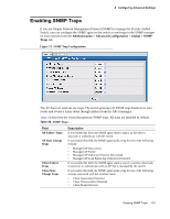
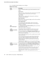
D-Link Unified Access System User Manual Table 53 describes the fields on the Wireless Global Configuration page. Table 53. General Global Configurations Field Peer Group ID Client Roam Timeout Ad Hoc Client Status AP Failure Status Client Failure Status RF Scan Status Tunnel IP MTU Size Description In order to support larger networks, you can configure Unified Switches as peers, with up to 4 switches in a peer group. Peer Unified Switches share some information about APs and allow L3 roaming among them. Peer Unified Switches are grouped according to the Group ID. This value determines how long to keep an entry in the Associated Client Status list after a client has disassociated. Each entry in the status list shows an age, and when the age reaches the value you configure in the timeout field, the entry is deleted. This value determines how long to keep an entry in the Ad Hoc Client Status list. Each entry in the status list shows an age, and when the age reaches the value you configure in the timeout field, the entry is deleted. This value determines how long to keep an entry in the AP Authentication Failure Status list. Each entry in the status list shows an age, and when the age reaches the value you configure in the timeout field, the entry is deleted. This value determines how long to keep an entry in the Client Authentication Failure Status list. Each entry in the status list shows an age, and when the age reaches the value you configure in the timeout field, the entry is deleted. This value determines how long to keep an entry in the RF Scan Status list. Each entry in the status list shows an age, and when the age reaches the value you configure in the timeout field, the entry is deleted. Sets the maximum size of the IP packet handled by the network. The MTU is enforced only on tunneled VAPs. Select one of the following values: • 1500: Maps the tunneled IP frame size to 1518 bytes (untagged) and 1522 bytes (tagged). Use this setting if your network does not support jumbo frames. Using 1500 as the Tunnel IP MTU size forces the D-Link Unified Access System to limit its maximum message size to 1518/1522 bytes. This setting directs the wireless system to mitigate the problem of oversized frames by enabling the MTU discovery protocol and limiting the maximum segment size in TCP connection setup messages. • 1520: Maps the tunneled IP frame size to 1538 bytes (untagged) and 1542 bytes (tagged). Use this setting if your network supports jumbo frames and you have configured the physical ports between the switch and the APs to support 1538/1542 byte packets. IP Packets that use the L3 tunnel have an extra 20 bytes in the header for encapsulation. This means that wireless clients configured with a 1500 byte IP MTU size may exceed the maximum MTU size of the existing network infrastructure if it is set up to switch and route 1518 (1522-tagged) byte frames. Setting the Network MTU Size to 1500 or 1520 does not affect physical port MTU size. The physical ports on the switch and the rest of the network devices must be configured with the appropriate MTU size. NOTE: If the AP is not connected directly to the wireless switch and the Tunnel IP MTU Size is set to 1520, any Ethernet segments in the path between the AP and the wireless switch must support jumbo frames and be configured for jumbo frames. 160 © 2001- 2008 D-Link Corporation. All Rights Reserved.
-
 1
1 -
2
-
3
-
4
-
5
-
6
-
7
-
8
-
9
-
10
-
11
-
12
-
13
-
14
-
15
-
16
-
17
-
18
-
19
-
20
-
21
-
22
-
23
-
24
-
25
-
26
-
27
-
28
-
29
-
30
-
31
-
32
-
33
-
34
-
35
-
36
-
37
-
38
-
39
-
40
-
41
-
42
-
43
-
44
-
45
-
46
-
47
-
48
-
49
-
50
-
51
-
52
-
53
-
54
-
55
-
56
-
57
-
58
-
59
-
60
-
61
-
62
-
63
-
64
-
65
-
66
-
67
-
68
-
69
-
70
-
71
-
72
-
73
-
74
-
75
-
76
-
77
-
78
-
79
-
80
-
81
-
82
-
83
-
84
-
85
-
86
-
87
-
88
-
89
-
90
-
91
-
92
-
93
-
94
-
95
-
96
-
97
-
98
-
99
-
100
-
101
-
102
-
103
-
104
-
105
-
106
-
107
-
108
-
109
-
110
-
111
-
112
-
113
-
114
-
115
-
116
-
117
-
118
-
119
-
120
-
121
-
122
-
123
-
124
-
125
-
126
-
127
-
128
-
129
-
130
-
131
-
132
-
133
-
134
-
135
-
136
-
137
-
138
-
139
-
140
-
141
-
142
-
143
-
144
-
145
-
146
-
147
-
148
-
149
-
150
-
151
-
152
-
153
-
154
-
 155
155 -
 156
156 -
 157
157 -
 158
158 -
 159
159 -
 160
160 -
 161
161 -
 162
162 -
 163
163 -
 164
164 -
 165
165 -
166
-
167
-
168
-
169
-
170
-
171
-
172
-
173
-
174
-
175
-
176
-
177
-
178
-
179
-
180
-
181
-
182
-
183
-
184
-
185
-
186
-
187
-
188
-
189
-
190
-
191
-
192
-
193
-
194
-
195
-
196
-
197
-
198
-
199
-
200
-
201
-
202
-
203
-
204
-
205
-
206
-
207
-
208
-
209
-
210
-
211
-
212
-
213
-
214
-
215
-
216
-
217
-
218
-
219
-
220
-
221
-
222
-
223
-
224
-
225
-
226
-
227
-
228
-
229
-
230
-
231
-
232
-
233
-
234
-
235
-
236
-
237
-
238
-
239
-
240
-
241
-
242
-
243
-
244
-
245
-
246
-
247
-
248
-
249
-
250
-
251
-
252
-
253
-
254
-
255
-
256
-
257
-
258
-
259
-
260
-
261
-
262
-
263
-
264
-
265
-
266
-
267
-
268
-
269
-
270
 |
 |
