DIRECTV D12MP Installation Guide - Page 39
Low-Speed Electrical Performance and Characteristics, 3 Low-Speed Input Characteristics
 |
View all DIRECTV D12MP manuals
Add to My Manuals
Save this manual to your list of manuals |
Page 39 highlights
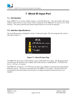
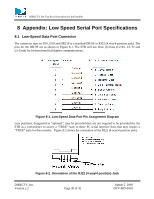
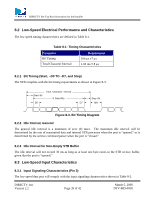
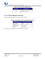
DIRECTV Set-Top Box Information for the Installer 8.2 Low-Speed Electrical Performance and Characteristics The low speed timing characteristics are defined in Table 8-1. Table 8-1: Timing Characteristics Parameter Bit Timing Total Character Interval Requirement 104 μs ±7 μs 1.04 ms ± 8 μs 8.2.1 Bit Timing (Start, -D0 TO -D7, and Stop) The STB complies with the bit timing requirements as shown in Figure 8-3. Start Bit Total Character Interval 8 Data Bits D0 D7 Stop Bit Idle Figure 8-3. Bit Timing Diagram 8.2.2 Idle Interval, General The general idle interval is a minimum of zero (0) msec. The maximum idle interval will be determined by the rate of transmitted data and internal STB processes when the port is "opened," or is determined by the service command parser when the port is "closed." 8.2.3 Idle Interval for Non-Empty STB Buffer The idle interval will not exceed 30 ms as long as at least one byte exists in the STB receive buffer, given that the port is "opened." 8.3 Low-Speed Input Characteristics 8.3.1 Input Signaling Characteristics (Pin 3) The low-speed data port will comply with the input signaling characteristics shown in Table 8-2. DIRECTV, Inc. Version 2.2 Page 39 of 42 March 5, 2008 DTV-MD-0058
-
 1
1 -
2
-
3
-
4
-
5
-
6
-
7
-
8
-
9
-
10
-
11
-
12
-
13
-
14
-
15
-
16
-
17
-
18
-
19
-
20
-
21
-
22
-
23
-
24
-
25
-
26
-
27
-
28
-
29
-
30
-
31
-
32
-
33
-
 34
34 -
 35
35 -
 36
36 -
 37
37 -
 38
38 -
 39
39 -
 40
40 -
 41
41 -
 42
42
 |
 |
