DIRECTV D12MP Installation Guide - Page 5

Table of s, List of Tables

Page 5 highlights

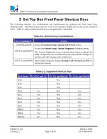
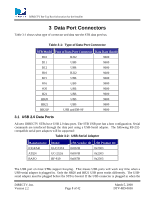
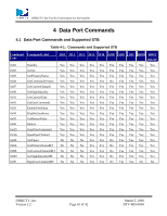
DIRECTV Set-Top Box Information for the Installer Table of Figures Figure 4-1. Service Command Parser Flowchart 14 Figure 6-1 RC32 remote control...34 Figure 7-1 Wired IR Input Plug ...37 Figure 8-1. Low-Speed Data Port Pin Assignment Diagram 38 Figure 8-2. Orientation of the RJ22 (4 way/4 position) Jack 38 Figure 8-3. Bit Timing Diagram...39 List of Tables Table 2-1: Shortcut Keys Combinations 7 Table 2-2: Supported Shortcut Keys...7 Table 3-1: Type of Data Port Connector 8 Table 3-2: USB-Serial Adapter ...8 Table 4-1: Commands and Supported STB 10 Table 4-2: Software Version of Supported STB 11 Table 4-3: Basic Commands Summary 12 Table 4-4: Multi-Tuner Commands Summary 13 Table 4-5: STB Responses List ...15 Table 8-1: Timing Characteristics ...39 Table 8-2: Input Drive Characteristics 40 Table 8-3: Output Drive Characteristics 40 Table 8-4: Passive Drive Characteristics 41 Table 8-5: Low-Speed Data Port Signaling Conventions 41 DIRECTV, Inc. Version 2.2 Page 5 of 42 March 5, 2008 DTV-MD-0058

  • 1
  • 2
  • 3
  • 4
  • 5
  • 6
  • 7
  • 8
  • 9
  • 10
  • 11
  • 12
  • 13
  • 14
  • 15
  • 16
  • 17
  • 18
  • 19
  • 20
  • 21
  • 22
  • 23
  • 24
  • 25
  • 26
  • 27
  • 28
  • 29
  • 30
  • 31
  • 32
  • 33
  • 34
  • 35
  • 36
  • 37
  • 38
  • 39
  • 40
  • 41
  • 42

DIRECTV Set-Top Box Information for the Installer
DIRECTV, Inc.
March 5, 2008
Version 2.2
Page 5 of 42
DTV-MD-0058
Table of Figures
Figure 4-1. Service Command Parser Flowchart
..................................................................................
14
Figure 6-1
RC32 remote control
. .........................................................................................................
34
Figure 7-1
Wired IR Input Plug
............................................................................................................
37
Figure 8-1. Low-Speed Data Port Pin Assignment Diagram
.................................................................
38
Figure 8-2. Orientation of the RJ22 (4 way/4 position) Jack
.................................................................
38
Figure 8-3. Bit Timing Diagram
.............................................................................................................
39
List of Tables
Table 2-1: Shortcut Keys Combinations
...................................................................................................
7
Table 2-2: Supported Shortcut Keys
.........................................................................................................
7
Table 3-1:
Type of Data Port Connector
.................................................................................................
8
Table 3-2:
USB-Serial Adapter
...............................................................................................................
8
Table 4-1:
Commands and Supported STB
...........................................................................................
10
Table 4-2:
Software Version of Supported STB
.....................................................................................
11
Table 4-3:
Basic Commands Summary
..................................................................................................
12
Table 4-4:
Multi-Tuner Commands Summary
.......................................................................................
13
Table 4-5:
STB Responses List
..............................................................................................................
15
Table 8-1: Timing Characteristics
.........................................................................................................
39
Table 8-2: Input Drive Characteristics
..................................................................................................
40
Table 8-3: Output Drive Characteristics
................................................................................................
40
Table 8-4: Passive Drive Characteristics
..............................................................................................
41
Table 8-5: Low-Speed Data Port Signaling Conventions
......................................................................
41