Dell Alienware 15 Service Manual - Page 118
Replacing the system board, Procedure
 |
View all Dell Alienware 15 manuals
Add to My Manuals
Save this manual to your list of manuals |
Page 118 highlights
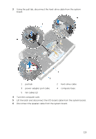
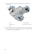
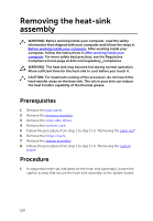
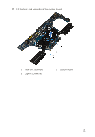
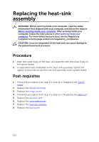
Replacing the system board WARNING: Before working inside your computer, read the safety information that shipped with your computer and follow the steps in Before working inside your computer. After working inside your computer, follow the instructions in After working inside your computer. For more safety best practices, see the Regulatory Compliance home page at dell.com/regulatory_compliance. NOTE: Your computer's Service Tag is stored in the system board. You must enter the Service Tag in the BIOS setup program after you replace the system board. NOTE: Replacing the system board removes any changes you have made to the BIOS using the BIOS setup program. You must make the desired changes again after you replace the system board. Procedure 1 Follow the procedure from step 1 to step 2 in "Replacing the coin-cell battery". 2 Follow the procedure from step 1 to step 2 in "Replacing the heat-sink assembly". 3 Turn the system board over. 4 Slide the ports on the system board into the slots on the computer base and align the screw holes on the system board with the screw holes on the computer base. CAUTION: Make sure that no cables are under the system board. 5 Replace the screws that secure the system board to the computer base. 6 Slide the I/O-board cable into the system board and press down on the latch to secure the cable. 7 Connect the speaker cable to the system board. 8 Connect the front AlienFX LED cable to the system board and secure it with the tape. 9 Turn the computer over. 10 Connect the fan cables, power-adapter port cable, and hard-drive cable to the system board. 11 Turn the computer over. 118
-
 1
1 -
2
-
3
-
4
-
5
-
6
-
7
-
8
-
9
-
10
-
11
-
12
-
13
-
14
-
15
-
16
-
17
-
18
-
19
-
20
-
21
-
22
-
23
-
24
-
25
-
26
-
27
-
28
-
29
-
30
-
31
-
32
-
33
-
34
-
35
-
36
-
37
-
38
-
39
-
40
-
41
-
42
-
43
-
44
-
45
-
46
-
47
-
48
-
49
-
50
-
51
-
52
-
53
-
54
-
55
-
56
-
57
-
58
-
59
-
60
-
61
-
62
-
63
-
64
-
65
-
66
-
67
-
68
-
69
-
70
-
71
-
72
-
73
-
74
-
75
-
76
-
77
-
78
-
79
-
80
-
81
-
82
-
83
-
84
-
85
-
86
-
87
-
88
-
89
-
90
-
91
-
92
-
93
-
94
-
95
-
96
-
97
-
98
-
99
-
100
-
101
-
102
-
103
-
104
-
105
-
106
-
107
-
108
-
109
-
110
-
111
-
112
-
 113
113 -
 114
114 -
 115
115 -
 116
116 -
 117
117 -
 118
118 -
 119
119 -
 120
120 -
 121
121 -
 122
122 -
 123
123 -
124
-
125
-
126
-
127
-
128
-
129
-
130
-
131
-
132
-
133
-
134
-
135
-
136
-
137
-
138
-
139
-
140
-
141
-
142
-
143
-
144
-
145
-
146
-
147
-
148
-
149
 |
 |