Dell Alienware Aurora R16 Owners Manual
Dell Alienware Aurora R16 Manual
 |
View all Dell Alienware Aurora R16 manuals
Add to My Manuals
Save this manual to your list of manuals |
Dell Alienware Aurora R16 manual content summary:
- Dell Alienware Aurora R16 | Owners Manual - Page 1
Alienware Aurora R16 Owner's Manual Regulatory Model: D30M Regulatory Type: D30M004 August 2023 Rev. A01 - Dell Alienware Aurora R16 | Owners Manual - Page 2
and tells you how to avoid the problem. WARNING: A WARNING indicates a potential for property damage, personal injury, or death. © 2023 Dell Inc. or its subsidiaries. All rights reserved. Dell Technologies, Dell, and other trademarks are trademarks of Dell Inc. or its subsidiaries. Other trademarks - Dell Alienware Aurora R16 | Owners Manual - Page 3
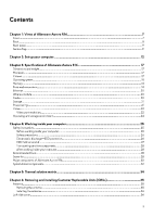
Contents Chapter 1: Views of Alienware Aurora R16 7 Front...7 Back...8 Back panel...9 Service Tag...11 Chapter 2: Set up your computer...12 Chapter 3: Specifications of Alienware Aurora R16 17 Dimensions and weight...17 Processor...17 Chipset...17 Operating system...18 Memory...18 Ports and - Dell Alienware Aurora R16 | Owners Manual - Page 4
Removing the left-side cover...36 Installing the left-side cover...37 Right-side cover...38 Removing the right-side cover...38 Installing the right-side cover...39 Front bezel ...40 Removing the front bezel...40 Installing the front bezel...42 Top cover...43 Removing the top cover...43 Installing - Dell Alienware Aurora R16 | Owners Manual - Page 5
Removing the system board...90 Installing the system board...93 Chapter 8: Alienware Command Center 98 Chapter 9: Software...99 Operating system...99 Drivers and Setup) and System passwords 109 Chapter 11: Troubleshooting...111 Dell SupportAssist Pre-boot System Performance Check diagnostics 111 - Dell Alienware Aurora R16 | Owners Manual - Page 6
Chapter 12: Getting help and contacting Alienware 114 6 - Dell Alienware Aurora R16 | Owners Manual - Page 7
Views of Alienware Aurora R16 Front 1. Power button (Alien head) Press to turn on the computer if it is turned off, in sleep state, or in hibernate state. Press to - Dell Alienware Aurora R16 | Owners Manual - Page 8
Gen 2 Type-C port with PowerShare Connect devices such as external storage devices and printers. Provides data transfer speed up to 10 Gbps. Supports Power Delivery that enables two-way power supply between devices. Provides up to 15 W power output that enables faster charging. PowerShare enables - Dell Alienware Aurora R16 | Owners Manual - Page 9
latch Pull the latch to quickly release the side panel from your computer. 4. Integrated external SMA card for optimal graphics performance. 10. Service Tag label The Service Tag is a unique alphanumeric identifier that enables Dell service technicians to identify the hardware components in - Dell Alienware Aurora R16 | Owners Manual - Page 10
a system from S0ix, S4, and S5 sleep states with a move of a mouse or press of a key on the keyboard. NOTE: This port does not support video/audio streaming or power delivery. 10. Network port (with lights) Connect an Ethernet (RJ45) cable from a router or a broadband modem for network or Internet - Dell Alienware Aurora R16 | Owners Manual - Page 11
Service Tag The service tag is a unique alphanumeric identifier that allows Dell service technicians to identify the hardware components in your computer and access warranty information. 11 - Dell Alienware Aurora R16 | Owners Manual - Page 12
on the configuration you ordered. Steps 1. Connect the wired keyboard and mouse to suitable ports. To connect a wireless keyboard and mouse, see the instructions on how to connect in the documentation that ships with the wireless keyboard and mouse. 2. Connect to your network using an Ethernet cable - Dell Alienware Aurora R16 | Owners Manual - Page 13
Wireless network: This computer is shipped with an external puck antenna. Connect the external antenna during setup, to connect to WiFi and Bluetooth and improve the memory performance, while setting up your operating system. To connect the SMA cables, follow the below procedure: a. Follow the - Dell Alienware Aurora R16 | Owners Manual - Page 14
Place the antenna in a suitable location. 14 - Dell Alienware Aurora R16 | Owners Manual - Page 15
3. Connect the display. For more information about setting up the display, see the documentation that is shipped with your display. NOTE: Connect the display to the discrete graphics card of your computer. 4. Connect the power cable to the computer and then connect it to the wall outlet. 15 - Dell Alienware Aurora R16 | Owners Manual - Page 16
5. Press the power button at the front of computer to turn on the computer. 16 - Dell Alienware Aurora R16 | Owners Manual - Page 17
depends on the configuration ordered and manufacturing variability. Processor The following table lists the details of the processors supported by your Alienware Aurora R16. Table 2. Processor Description Processor type Option one 13th Generation Intel Core i7-13700F Option two 13th Generation - Dell Alienware Aurora R16 | Owners Manual - Page 18
Values ● 13th Generation Intel Core i7/i9 ● 12th Generation Intel Core i9 128-bit 32 MB Up to Gen5 Operating system Your Alienware Aurora R16 supports the following operating systems: ● Windows 11 Pro, 64-bit ● Windows 11 Home, 64-bit Memory The following table lists the memory specifications - Dell Alienware Aurora R16 | Owners Manual - Page 19
stack ● One side L/R surround port - 3.5 mm, 6 stack Supported through discrete GPU Not supported 110 V/220 V ● One security-cable slot (wedge-shaped) PCIe x16 mechanical/x16 electrical Gen5 slot ● Two PCIe Gen3 x4 slots Not supported Two ● One M.2 2230 slot for WiFi and Bluetooth combo card ● Two - Dell Alienware Aurora R16 | Owners Manual - Page 20
/100/1000/2500 Mbps Wireless module The following table lists the Wireless Local Area Network (WLAN) modules that are supported on your Alienware Aurora R16. Table 7. Wireless module specifications Description Option one Model number Intel AX210 Option two Intel Killer AX1675x Transfer rate - Dell Alienware Aurora R16 | Owners Manual - Page 21
8. Audio specifications (continued) Description Values ● Coaxial S/PDIF ● Headset Storage This section lists the storage options on your Alienware Aurora R16. Your Alienware Aurora R16 supports one of the following storage configurations: ● Up to two M.2 2280 PCIe NVMe solid-state drives ● Up to - Dell Alienware Aurora R16 | Owners Manual - Page 22
The following table lists the detailed discrete graphics specifications of your Alienware Aurora R16. Table 11. Discrete graphics specifications Discrete graphics Controller Number of cards External display support Memory size Memory type PCIe version Power consumption NVIDIA 1 GeForce RTX - Dell Alienware Aurora R16 | Owners Manual - Page 23
GeForce RTX 4070 Ti ● Three DisplayPort 1.4a ports1 ● One HDMI 2.1a port NVIDIA GeForce RTX 4080 ● Three DisplayPort 1.4a ports1 ● One HDMI 2.1a port Maximum supported resolution ● 7680 x 4320 at 120 Hz4 ● 7680 x 4320 at 60 Hz5 ● 7680 x 4320 at 60 Hz6 ● 5120 x 3200 at 60 Hz7 ● 5120 x 2880 at 60 - Dell Alienware Aurora R16 | Owners Manual - Page 24
12. Video port resolution (continued) Graphics card Video ports Maximum supported resolution 1 DisplayPort 1.2 certified, DisplayPort 1.3/1.4 ready. 2 Depending table lists the operating and storage specifications of your Alienware Aurora R16. Airborne contaminant level: G1 as defined by ISA- - Dell Alienware Aurora R16 | Owners Manual - Page 25
and the contacts. CAUTION: You should only perform troubleshooting and repairs as authorized or directed by the Dell technical assistance team. Damage due to servicing that is not authorized by Dell is not covered by your warranty. See the safety instructions that is shipped with the product or at - Dell Alienware Aurora R16 | Owners Manual - Page 26
disassembly instructions. ESD field service kit when working inside any desktop to obvious, such as intermittent problems or a shortened product Dell products, the sensitivity to static damage is now higher than in previous Dell of damage to recognize and troubleshoot is the intermittent (also called - Dell Alienware Aurora R16 | Owners Manual - Page 27
a desktop or portable environment. Servers are typically installed in a rack within a data center; desktops or part using the same ESD bag and packaging that the new part arrived in. The ESD bag should be folded over at all times when servicing Dell products. In addition, it is critical to - Dell Alienware Aurora R16 | Owners Manual - Page 28
Transporting sensitive components When transporting ESD sensitive components such as replacement parts or parts to be returned to Dell, it is critical to place these parts in anti-static bags for safe transport. After working inside your computer About this task CAUTION: Leaving stray - Dell Alienware Aurora R16 | Owners Manual - Page 29
Table 14. Screw list (continued) Component Screw type Power-supply unit (for computers shipped with clear left-side cover) #6-32x1/4" Radiator and fan assembly for liquid cooler M3x5 Rear-chassis fan M3x5 Lower front-chassis fan M3x5 Solid-state drive (M.2 slot one/ slot two) Wireless - Dell Alienware Aurora R16 | Owners Manual - Page 30
Major components of Alienware Aurora R16 1. Front bezel 30 2. Left-side cover - Dell Alienware Aurora R16 | Owners Manual - Page 31
3. Coin-cell battery 5. Liquid-cooling assembly (optional) 7. M.2 2230 solid-state drive (sold separately) 9. Chassis 11. Power-supply unit 13. VR heat sink 15. Lower front-chassis fan 17. Processor fan and heat-sink assembly (optional) 19. Graphics-card bracket (optional) 21. Processor 23. SMA - Dell Alienware Aurora R16 | Owners Manual - Page 32
System-board components 1. Coin-cell battery 3. SATA 6 Gbps drive connector (HDD1) 5. Power-supply connector (ATX1) 7. Solid-state drive slot (M.2 PCIe SSD-1) 9. Memory-module slot, DIMM2 11. PCI-Express x16 mechanical/x16 electrical slot (SLOT1) 13. PCI-Express x4 slot (SLOT2) 15. Rear-chassis fan - Dell Alienware Aurora R16 | Owners Manual - Page 33
19. Power-supply connector (ATX3) 21. Air-cooling fan connector (FAN CPU) 23. SATA power connector (SATA PWR) 25.Front I/O-panel cable 20.Power-supply connector (ATX2) 22. Top-chassis fan connector two (FAN_SYS5) 24.Wireless-card slot 33 - Dell Alienware Aurora R16 | Owners Manual - Page 34
Thermal solution matrix Table 15. Thermal solution matrix Processor Power supply Intel i7,i9 series non-K processors (65 W) 500 W Intel i7,i9 series non-K processors (65 W) 1000 W Graphics card power consumption Up to 225 W Up to 225 W Up to 225 Up to 400 Up to 400 W W W Graphics card ● - Dell Alienware Aurora R16 | Owners Manual - Page 35
Removing and installing Customer Replaceable Units (CRUs) The replaceable components in this chapter are Customer Replaceable Units (CRUs). CAUTION: Customers can replace only the Customer Replaceable Units (CRUs) following the safety precautions and replacement procedures. NOTE: The images in this - Dell Alienware Aurora R16 | Owners Manual - Page 36
Installing the antenna About this task This computer is shipped with an external puck antenna. Connect the external antenna during setup, to connect to WiFi and Bluetooth and improve the memory performance. To connect the SMA cables, follow the below procedure. Steps 1. Align and connect the SMA - Dell Alienware Aurora R16 | Owners Manual - Page 37
Steps 1. Loosen the captive screw (#6-32) that secures the side-cover release latch to the chassis. 2. Pull the side-cover release latch to release the left-side cover away from the chassis. 3. Lift the left-side panel from the chassis. Installing the left-side cover Prerequisites If you are - Dell Alienware Aurora R16 | Owners Manual - Page 38
. 2. Rotate the left-side cover towards the chassis until it snaps into place. 3. Tighten the captive screw (#6-32) that secures the side-cover release latch to the chassis. Next steps 1. Follow the procedure in After working inside your computer. Right-side cover Removing the right-side cover - Dell Alienware Aurora R16 | Owners Manual - Page 39
Steps Pull and lift the right-side cover away from the chassis. Installing the right-side cover Prerequisites If you are replacing a component, remove the existing component before performing the installation procedure. About this task The following images indicate the location of the right-side - Dell Alienware Aurora R16 | Owners Manual - Page 40
Steps 1. Align the tabs on the right-side cover with the slots on the chassis. 2. Push the right-side cover towards the chassis until it snaps into place. Next steps 1. Install the left-side cover. 2. Follow the procedure in After working inside your computer. Front bezel Removing the front bezel - Dell Alienware Aurora R16 | Owners Manual - Page 41
Steps 1. Place the computer in an upright position. 2. Disconnect the front I/O-panel cable from the system board. 3. Remove the four screws (#6-32x1/4") that secures the front bezel to the front panel. 4. Pull the tabs of the front bezel from the slots on the front panel. NOTE: Start with tab on - Dell Alienware Aurora R16 | Owners Manual - Page 42
Installing the front bezel Prerequisites If you are replacing a component, remove the existing component before performing the installation procedure. About this task The following images indicate the location of the front bezel and provide a visual representation of the installation procedure. - Dell Alienware Aurora R16 | Owners Manual - Page 43
2. Route the front I/O-panel cable through the slot on the front panel. 3. Push the front bezel towards the front panel and ensure the tabs clip on to the slots of the front panel. NOTE: Start with tab on top, proceed to the tabs on the left of the front bezel, and then to the tabs on the right of - Dell Alienware Aurora R16 | Owners Manual - Page 44
Steps Press down the latch from front side, and push/slide the cover toward to rear side, then lift the cover up. NOTE: The top cover is secured tight to the chassis by four latches. Installing the top cover Prerequisites If you are replacing a component, remove the existing component before - Dell Alienware Aurora R16 | Owners Manual - Page 45
Steps Align the tabs on the top cover with the slots on the chassis and snap the top cover into place. Next steps 1. Install the front bezel. 2. Install the right-side cover. 3. Install the left-side cover. 4. Follow the procedure in After working inside your computer. 3.5-inch hard drive Removing - Dell Alienware Aurora R16 | Owners Manual - Page 46
representation of the removal procedure. Steps 1. Lay the computer on the right side. 2. Disconnect the data and power cables from the hard drive. 3. Press the release tabs on the hard-drive carrier and slide the hard-drive carrier out of the hard-drive cage. 4. Pry the hard-drive carrier to - Dell Alienware Aurora R16 | Owners Manual - Page 47
NOTE: Note the orientation of the hard drive so that you can replace it correctly. Installing the 3.5-inch hard drive Prerequisites If you are replacing a component, remove the existing component before performing the installation procedure. About this task The following images indicate the location - Dell Alienware Aurora R16 | Owners Manual - Page 48
Steps 1. Align the hard drive with the pins on the hard-drive carrier. 2. Using the tabs on the opposite side, flex open the carrier to insert the pins on the other side. 3. Slide the hard-drive assembly into the hard-drive cage until it snaps into place. 4. Connect the data and power cables to the - Dell Alienware Aurora R16 | Owners Manual - Page 49
(BIOS). NOTE: To install the operating system on to your storage device, see Reinstall Windows to the Dell factory image using recovery media in the Knowledge Base Resource at www.dell.com/support. Identifying the storage device in Device Manager Steps 1. On the taskbar, click the search box, and - Dell Alienware Aurora R16 | Owners Manual - Page 50
Steps 1. Lay the computer on the right side. 2. Press the battery-release lever away from the coin-cell battery until the coin-cell battery pops up. 3. Lift the coin-cell battery out of its socket. Installing the - Dell Alienware Aurora R16 | Owners Manual - Page 51
Steps Insert the new coin-cell battery (CR2032) into the battery socket with the positive side facing up, and snap the battery into place. Next steps 1. Install the left- - Dell Alienware Aurora R16 | Owners Manual - Page 52
Steps 1. Lay the computer on the right side. 2. Push the securing clips away from the memory module. 3. Lift the memory module off the memory-module slot. NOTE: Repeat step 2 to step 3 to remove any other memory modules installed in your computer. CAUTION: To prevent damage to the memory module, - Dell Alienware Aurora R16 | Owners Manual - Page 53
Steps 1. Ensure that the securing clips are extended away from the memory-module slot. 2. Align the notch on the memory module with the tab on the memory-module slot. 3. Insert the memory module into the memory-module slot and press the memory module down until it snaps into position and the - Dell Alienware Aurora R16 | Owners Manual - Page 54
procedure. Steps 1. Lay the computer on the right side. 2. Slide the release latch to its unlock position and lift the graphics-card end holder away card does not ship with a graphics-card end holder. 3. Slide the release latch to its unlock position and lift the graphics-card bracket away from the - Dell Alienware Aurora R16 | Owners Manual - Page 55
4. Press the releasing clip on the graphics-card power connectors and disconnect the graphics-card power cables from the graphics card. 5. Lift the pull tab and open the - Dell Alienware Aurora R16 | Owners Manual - Page 56
end holder The following table shows whether the graphics-card bracket or/and the graphics-card end holder is/are shipped with your Alienware Aurora R16. Table 17. Graphics-card bracket and graphics-card end holder Graphics card NVIDIA GeForce RTX 3050 Graphics-card bracket No Graphics-card end - Dell Alienware Aurora R16 | Owners Manual - Page 57
in SSD slot one/slot two. NOTE: The M.2 2230 solid-state drives are sold separately. NOTE: Depending on the configuration ordered, your computer may support either a M.2 2230 solid-state drive or a M.2 2280 solid-state drive in SSD slot one/slot two. If you want to replace your M.2 2230 solid - Dell Alienware Aurora R16 | Owners Manual - Page 58
). NOTE: To install the operating system on to your storage device, see Reinstall Windows to the Dell factory image using recovery media in the Knowledge Base Resource at www.dell.com/support. Removing the M.2 2280 solid-state drive Prerequisites 1. Follow the procedure in Before working inside your - Dell Alienware Aurora R16 | Owners Manual - Page 59
to computers shipped with a M.2 2280 solid-state drive installed in SSD slot one/slot two. NOTE: Depending on the configuration ordered, your computer may support either a M.2 2280 solid-state drive or a M.2 2230 solid-state drive in SSD slot one/slot two. If you want to replace your M.2 2280 solid - Dell Alienware Aurora R16 | Owners Manual - Page 60
NOTE: To install the operating system on to your storage device, see Reinstall Windows to the Dell factory image using recovery media in the Knowledge Base Resource at www.dell.com/support. Wireless card Removing the wireless card Prerequisites 1. Follow the procedure in Before working inside your - Dell Alienware Aurora R16 | Owners Manual - Page 61
Steps 1. Lay the computer on the right side. 2. Remove the screw (M2x3) that secures the wireless card to the system board. 3. Lift the wireless-card bracket off the wireless card. 4. Disconnect the SMA cables from the wireless card. 5. Slide and remove the wireless card from the wireless-card slot. - Dell Alienware Aurora R16 | Owners Manual - Page 62
inside your computer. Lower front-chassis fan Removing the lower front-chassis fan CAUTION: The information in this removal section is intended for authorized service technicians only. Prerequisites 1. Follow the procedure in Before working inside your computer. 2. Remove the left-side cover. 62 - Dell Alienware Aurora R16 | Owners Manual - Page 63
task The following images indicate the location of the lower front-chassis fan and provide a visual representation of the removal procedure. Steps 1. Slide the release latch to its unlock position and lift the graphics-card end holder away from the PCIe fan. NOTE: Skip this step if your graphics - Dell Alienware Aurora R16 | Owners Manual - Page 64
5. Push the tab to release the lower front-chassis fan from the chassis. 6. Slide and lift the lower front-chassis fan off the chassis. Installing the lower front-chassis fan CAUTION: The information in this installation section is intended for authorized service technicians only. Prerequisites If - Dell Alienware Aurora R16 | Owners Manual - Page 65
its right side. 2. Align the tabs on the lower front-chassis fan with the slots on the chassis. 3. Slide and push the fan until the releasing clip snaps into position on the chassis. 4. Replace the screw (M3x5) that secures the lower front-chassis fan to the chassis. 5. Connect the lower front - Dell Alienware Aurora R16 | Owners Manual - Page 66
inside your computer. Rear-chassis fan Removing the rear-chassis fan CAUTION: The information in this removal section is intended for authorized service technicians only. Prerequisites 1. Follow the procedure in Before working inside your computer. 2. Remove the left-side cover. About this task The - Dell Alienware Aurora R16 | Owners Manual - Page 67
-chassis off the chassis. Installing the rear-chassis fan CAUTION: The information in this installation section is intended for authorized service technicians only. Prerequisites If you are replacing a component, remove the existing component before performing the installation procedure. About this - Dell Alienware Aurora R16 | Owners Manual - Page 68
the top-chassis fan cables from the system board. 3. Remove the two screws (M3x5) that secures the top-chassis fan to the chassis. 4. Press the releasing clip of the top-chassis fan. 5. Slide and lift the top-chassis fan off the chassis. 68 - Dell Alienware Aurora R16 | Owners Manual - Page 69
Installing the top-chassis fan About this task The following images indicate the location of the top-chassis fan and provide a visual representation of the installation procedure. Steps 1. Lay the computer on the right side. 2. Align and place the top-chassis fan on the chassis. 3. Connect the top- - Dell Alienware Aurora R16 | Owners Manual - Page 70
only. CAUTION: To avoid any potential damage to the component or loss of data, ensure that an authorized service technician replaces the Field Replaceable Units (FRUs). CAUTION: Dell Technologies recommends that this set of repairs, if needed, to be conducted by trained technical repair specialists - Dell Alienware Aurora R16 | Owners Manual - Page 71
Steps 1. Lay the computer on the right side. 71 - Dell Alienware Aurora R16 | Owners Manual - Page 72
the graphics-card power cables from the power- supply unit. 7. Slide the release latch to the unlock position and lift the graphics-card bracket away from the information in this installation section is intended for authorized service technicians only. Prerequisites If you are replacing a component - Dell Alienware Aurora R16 | Owners Manual - Page 73
the two screws (#6-32x1/4") that secure the power-supply unit bracket to the power-supply unit. 7. Replace the graphics-card bracket and slide the release latch to the lock position. 8. Route the power-supply unit cables through the securing clip. 9. Connect the power-supply cables to the system - Dell Alienware Aurora R16 | Owners Manual - Page 74
heat-sink assembly Removing the processor fan and heat-sink assembly CAUTION: The information in this removal section is intended for authorized service technicians only. Prerequisites 1. Follow the procedure in Before working inside your computer. NOTE: The heat sink may become hot during normal - Dell Alienware Aurora R16 | Owners Manual - Page 75
. Installing the processor fan and heat-sink assembly CAUTION: The information in this installation section is intended for authorized service technicians only. Prerequisites If you are replacing a component, remove the existing component before performing the installation procedure. CAUTION: If - Dell Alienware Aurora R16 | Owners Manual - Page 76
-cooling assembly Removing the processor liquid-cooling assembly CAUTION: The information in this removal section is intended for authorized service technicians only. Prerequisites 1. Follow the procedure in Before working inside your computer. WARNING: Despite having a plastic shield, the processor - Dell Alienware Aurora R16 | Owners Manual - Page 77
captive screws that secure the processor-cooling assembly to the system board. 6. Release the spring latch and lift the processor-cooling assembly, along with the cables information in this installation section is intended for authorized service technicians only. Prerequisites If you are replacing a - Dell Alienware Aurora R16 | Owners Manual - Page 78
About this task The following images indicate the location of the processor liquid-cooling assembly and provide a visual representation of the installation procedure. Steps 1. Align the screw hole of the radiator and fan assembly to the screw hole on the chassis and ensure that the spring latch is - Dell Alienware Aurora R16 | Owners Manual - Page 79
Liquid-cooling assembly fan Removing the liquid-cooling assembly fan CAUTION: The information in this removal section is intended for authorized service technicians only. Prerequisites 1. Follow the procedure in Before working inside your computer. 2. Remove the left-side cover. About this task The - Dell Alienware Aurora R16 | Owners Manual - Page 80
-cooling assembly. Installing the liquid-cooling assembly fan CAUTION: The information in this installation section is intended for authorized service technicians only. Prerequisites If you are replacing a component, remove the existing component before performing the installation procedure. About - Dell Alienware Aurora R16 | Owners Manual - Page 81
in After working inside your computer. Processor Removing the processor CAUTION: The information in this removal section is intended for authorized service technicians only. Prerequisites 1. Follow the procedure in Before working inside your computer. 2. Remove the left-side cover. 3. Remove the - Dell Alienware Aurora R16 | Owners Manual - Page 82
it from the tab. 2. Extend the release lever completely and open the processor cover. 3. Lift the processor off the processor socket. Installing the processor CAUTION: The information in this installation section is intended for authorized service technicians only. Prerequisites If you are replacing - Dell Alienware Aurora R16 | Owners Manual - Page 83
-cover notch is positioned underneath the alignment post. 3. When the processor is fully seated in the socket, close the processor cover. 4. Push the release lever down and place it under the tab on the processor cover. Next steps 1. Install the processor liquid-cooling assembly or processor fan and - Dell Alienware Aurora R16 | Owners Manual - Page 84
SMA cable Removing the SMA cable CAUTION: The information in this removal section is intended for authorized service technicians only. Prerequisites 1. Follow the procedure in Before working inside your computer. 2. Remove the left-side cover. 3. Remove the single-graphics card. 4. Remove the - Dell Alienware Aurora R16 | Owners Manual - Page 85
Steps 1. Remove the washer and nuts that secure the SMA cable connector to the chassis. 2. Route the SMA cable assembly through the slot on the rear I/O. 3. Remove the SMA cable from the securing clip on the system board. 4. Remove the SMA cable routing from the PCIe x16 slot. 5. Lift the SMA cable - Dell Alienware Aurora R16 | Owners Manual - Page 86
Installing the SMA cable CAUTION: The information in this installation section is intended for authorized service technicians only. Prerequisites If you are replacing a component, remove the existing component before performing the installation procedure. About this task The following images - Dell Alienware Aurora R16 | Owners Manual - Page 87
inside your computer. VR heat sink Removing the VR heat sink CAUTION: The information in this removal section is intended for authorized service technicians only. Prerequisites 1. Follow the procedure in Before working inside your computer. NOTE: The heat sink may become hot during normal operation - Dell Alienware Aurora R16 | Owners Manual - Page 88
NOTE: The VR heat sinks (2) are shipped as separate units and they do not ship along with the new system board. Remove the VR heat sink (2) from old system board for transfer to the new system board. 2. Remove the left-side cover. About this task The following images indicate the location of the - Dell Alienware Aurora R16 | Owners Manual - Page 89
The information in this installation section is intended for authorized service technicians only. Prerequisites If you are replacing a component, component before performing the installation procedure. NOTE: Before installing the new VR heat sink, ensure to remove the protective foil from the - Dell Alienware Aurora R16 | Owners Manual - Page 90
technicians only. Prerequisites 1. Follow the procedure in Before working inside your computer. NOTE: Your computer's Service Tag is stored in the system board. You must enter the Service Tag in the BIOS setup program after you replace the system board. NOTE: Replacing the system board removes - Dell Alienware Aurora R16 | Owners Manual - Page 91
5. Remove the memory module. 6. Remove the single-graphics card. 7. Remove the M.2 2230 solid-state drive or the M.2 2280 solid-state drive in SSD slot one or slot two, as applicable. 8. Remove the wireless card. 9. Remove the processor liquid-cooling assembly or processor fan and heat-sink assembly - Dell Alienware Aurora R16 | Owners Manual - Page 92
3. SATA 6 Gbps drive connector (HDD1) 5. Power-supply connector (ATX1) 7. Solid-state drive slot (M.2 PCIe SSD-1) 9. Memory-module slot, DIMM2 11. PCI-Express x16 mechanical/x16 electrical slot (SLOT1) 13. PCI-Express x4 slot (SLOT2) 15. Rear-chassis fan LED connector (LED FAN SYS1) 17. Liquid- - Dell Alienware Aurora R16 | Owners Manual - Page 93
the system board from the chassis. Installing the system board CAUTION: The information in this installation section is intended for authorized service technicians only. Prerequisites If you are replacing a component, remove the existing component before performing the installation procedure. 93 - Dell Alienware Aurora R16 | Owners Manual - Page 94
About this task The following image indicates the connectors on your system board. 1. Coin-cell battery 3. SATA 6 Gbps drive connector (HDD1) 5. Power-supply connector (ATX1) 7. Solid-state drive slot (M.2 PCIe SSD-1) 9. Memory-module slot, DIMM2 11. PCI-Express x16 mechanical/x16 electrical slot ( - Dell Alienware Aurora R16 | Owners Manual - Page 95
19. Power-supply connector (ATX3) 21. Air-cooling fan connector (FAN CPU) 23. SATA power connector (SATA PWR) 25.Front I/O-panel cable 20.Power-supply connector (ATX2) 22. Top-chassis fan connector two (FAN_SYS5) 24.Wireless-card slot The following images indicate the location of the system board - Dell Alienware Aurora R16 | Owners Manual - Page 96
Steps 1. Slide the front I/O-ports on the system board into the front I/O-slot on the chassis and align the screw holes on the system board with the standoffs on the chassis. 2. Place the system board on the standoffs on the chassis. 3. Align the front I/O-bracket to the front I/O-ports and install - Dell Alienware Aurora R16 | Owners Manual - Page 97
7. Install the memory module. 8. Install the front bezel. 9. Install the right-side cover. 10. Install the left-side cover. 11. Follow the procedure in After working inside your computer. 97 - Dell Alienware Aurora R16 | Owners Manual - Page 98
Alienware gaming experience. AWCC also supports AlienFX 2.0. AlienFX enables available in AWCC. AWCC supports the following features: ● Alienware Command Center. Supports supports Sound Management, Thermal Controls, CPU, GPU, Memory (RAM) monitoring. For more information about AWCC, see the Alienware - Dell Alienware Aurora R16 | Owners Manual - Page 99
instructions on how to install the drivers. Operating system Your Alienware Aurora R16 supports the following operating systems: ● Windows 11 Pro, 64-bit ● Windows 11 Home, 64-bit Drivers and downloads When troubleshooting, downloading or installing drivers it is recommended that you read the Dell - Dell Alienware Aurora R16 | Owners Manual - Page 100
BIOS setup CAUTION: Unless you are an expert computer user, do not change the settings in the BIOS Setup program. Certain changes can make your computer work incorrectly. NOTE: Depending on the computer and its installed devices, the items listed in this section may or may not be displayed. NOTE: - Dell Alienware Aurora R16 | Owners Manual - Page 101
Displays the current date in mm/dd/yy format. Displays the BIOS version number. Displays the product name. Default: Alienware Aurora R16 Displays the service tag of your HyperThread Control HyperThread Control Multiple-Core Support Multiple-Core Support Enables or disables Intel(R)SpeedStep. - Dell Alienware Aurora R16 | Owners Manual - Page 102
Register (BAR) feature. Default: Disabled IPv4 HTTP Support IPv4 HTTP Support Allows you to enable or disable IPv4 HTTP Support. Default: Disabled IPv6 HTTP Support IPv6 HTTP Support Allows you to enable or disable IPv6 HTTP Support. Default: Disabled USB Configuration Front USB Ports Allows - Dell Alienware Aurora R16 | Owners Manual - Page 103
On Mode Allows you to set the computer to turn on automatically every day or on a preselected date. This option can be configured only if the Auto Power On mode is set to Enabled Everyday or boot flow for SupportAssist System Resolution Console and for Dell operating system Recovery tool. 103 - Dell Alienware Aurora R16 | Owners Manual - Page 104
Table (WSMT) Enable Pre-Boot DMA Protection Enable OS Kernel DMA Support Secure Boot Displays the unlock setup status. Displays whether the admin the BIOS module interface of the optional Absolute Persistence Module service from Absolute Software. Default: Enabled Displays the firmware TPM - Dell Alienware Aurora R16 | Owners Manual - Page 105
Table 21. System setup options-Security menu (continued) Security Secure Boot Enables secure boot using only validated boot software. Default: Disabled Secure Boot Mode Modifies the behavior of Secure Boot to allow evaluation or enforcement of UEFI driver signatures. Deployed Mode should be - Dell Alienware Aurora R16 | Owners Manual - Page 106
in Windows Steps 1. Go to www.dell.com/support. 2. Click Product support. In the Search support box, enter the Service Tag of your computer, and then press Enter. The BIOS Update Utility appears. 8. Follow the on-screen instructions to complete the BIOS update. Updating the BIOS from the F12 One - Dell Alienware Aurora R16 | Owners Manual - Page 107
have to be bootable) ● BIOS executable file that you downloaded from the Dell Support website and copied to the root of the USB drive ● AC power adapter is disabled. Assigning a system setup password Prerequisites You can assign a new System or Admin Password only when the status is in Not Set. - Dell Alienware Aurora R16 | Owners Manual - Page 108
Password, update, or delete the existing setup password, and press Enter or Tab. NOTE: If you change the System and/or Setup password, reenter the new password when prompted. If you delete the System and/or Setup password, confirm the deletion when prompted. 5. Press Esc and a message prompts you to - Dell Alienware Aurora R16 | Owners Manual - Page 109
Steps 1. Turn off the computer and disconnect the power cable from the computer. 2. Remove the left-side cover. 3. Lay the computer on its right side. 4. Locate the 2-pin CMOS jumper on the system board. 5. Ensure that the jumper is on the pair of password pins (JM34). 6. Move the jumper to the pair - Dell Alienware Aurora R16 | Owners Manual - Page 110
(JM34) and remove the jumper. 6. Plug the power cable to the computer and turn on the computer to clear the password. 7. Wait for until the desktop is loaded and then shut down the computer. 8. Disconnect the power cable from the computer. 9. Replace the jumper on the pair of password pins (JM34 - Dell Alienware Aurora R16 | Owners Manual - Page 111
Troubleshooting Dell SupportAssist Pre-boot System Performance Check diagnostics About this task SupportAssist diagnostics (also known as system diagnostics) performs a complete check of your hardware. The Dell error messages that inform you of problems encountered during testing NOTE: Some tests - Dell Alienware Aurora R16 | Owners Manual - Page 112
codes and recommended solutions are intended for Dell service technicians to troubleshoot problems. You should only perform troubleshooting and repairs as authorized or directed by the Dell technical support team. Damage due to servicing that is not authorized by Dell is not covered by your warranty - Dell Alienware Aurora R16 | Owners Manual - Page 113
The following procedure provides the instructions on how to conduct a Wi-Fi power cycle: NOTE: Some ISPs (Internet Service Providers) provide a modem/ known as a performing a "hard reset", is also a common troubleshooting step if your computer does not power on or boot into www.dell.com/ support. 113 - Dell Alienware Aurora R16 | Owners Manual - Page 114
computer through videos, manuals and documents. Videos providing step-by-step instructions to service your computer In Windows search, type Contact Support, and press Enter. www.dell.com/support/windows Your Alienware computer is uniquely identified by a Service Tag or Express Service Code. To view
-
 1
1 -
 2
2 -
 3
3 -
 4
4 -
 5
5 -
 6
6 -
 7
7 -
8
-
9
-
10
-
11
-
12
-
13
-
14
-
15
-
16
-
17
-
18
-
19
-
20
-
21
-
22
-
23
-
24
-
25
-
26
-
27
-
28
-
29
-
30
-
31
-
32
-
33
-
34
-
35
-
36
-
37
-
38
-
39
-
40
-
41
-
42
-
43
-
44
-
45
-
46
-
47
-
48
-
49
-
50
-
51
-
52
-
53
-
54
-
55
-
56
-
57
-
58
-
59
-
60
-
61
-
62
-
63
-
64
-
65
-
66
-
67
-
68
-
69
-
70
-
71
-
72
-
73
-
74
-
75
-
76
-
77
-
78
-
79
-
80
-
81
-
82
-
83
-
84
-
85
-
86
-
87
-
88
-
89
-
90
-
91
-
92
-
93
-
94
-
95
-
96
-
97
-
98
-
99
-
100
-
101
-
102
-
103
-
104
-
105
-
106
-
107
-
108
-
109
-
110
-
111
-
112
-
113
-
114
 |
 |

Alienware Aurora R16
Owner's Manual
Regulatory Model: D30M
Regulatory Type: D30M004
August 2023
Rev. A01