Dell D630 Service Manual - Page 21
Port Covers - screen replacement
 |
UPC - 019801087219
View all Dell D630 manuals
Add to My Manuals
Save this manual to your list of manuals |
Page 21 highlights
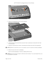
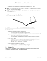
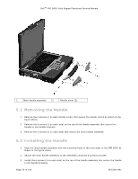
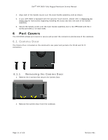
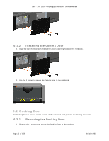
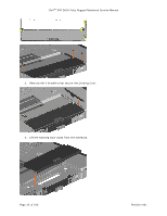
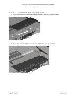
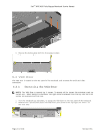
DellTM XFR D630 Fully Rugged Notebook Service Manual 4. Align each of the handle covers over the main handle assembly ends as shown. 5. If your XFR D630 is equipped with the optional Touch Screen, please refer to Replacing the 97H Stylus Clip for instructions regarding installing the stylus clip onto one side of the handle assembly. 6. Secure the handle covers over the main handle assembly and to the XFR D630 with the 4 screws provided (2 on each side). 6 Port Covers The XFR D630 utilizes port covers to secure and protect the connectors and devices of the notebook. 6.1 Comms Door The Comms Door is located on the notebook's rear panel and protects the RJ-45 and RJ-11 connectors. 6.1.1 Removing the Comms Door 1. Remove the 2 screws that secure the Comms Door. 2. Remove the Comms Door from the notebook. Page 21 of 106 Revision A01
-
 1
1 -
2
-
3
-
4
-
5
-
6
-
7
-
8
-
9
-
10
-
11
-
12
-
13
-
14
-
15
-
 16
16 -
 17
17 -
 18
18 -
 19
19 -
 20
20 -
 21
21 -
 22
22 -
 23
23 -
 24
24 -
 25
25 -
 26
26 -
27
-
28
-
29
-
30
-
31
-
32
-
33
-
34
-
35
-
36
-
37
-
38
-
39
-
40
-
41
-
42
-
43
-
44
-
45
-
46
-
47
-
48
-
49
-
50
-
51
-
52
-
53
-
54
-
55
-
56
-
57
-
58
-
59
-
60
-
61
-
62
-
63
-
64
-
65
-
66
-
67
-
68
-
69
-
70
-
71
-
72
-
73
-
74
-
75
-
76
-
77
-
78
-
79
-
80
-
81
-
82
-
83
-
84
-
85
-
86
-
87
-
88
-
89
-
90
-
91
-
92
-
93
-
94
-
95
-
96
-
97
-
98
-
99
-
100
-
101
-
102
-
103
-
104
-
105
-
106
 |
 |
