Dell D630 Service Manual - Page 54
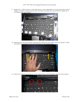
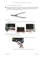
memory module connector until the module pops up.
 |
UPC - 019801087219
View all Dell D630 manuals
Add to My Manuals
Save this manual to your list of manuals |
Page 54 highlights
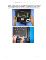
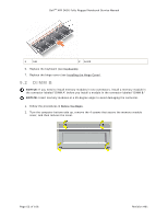
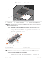
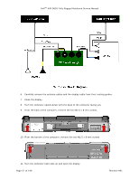
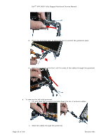
DellTM XFR D630 Fully Rugged Notebook Service Manual 1 3 2 1 Screws (4) 2 Memory module cover 3 Memory module compartment NOTICE: To prevent damage to the memory module connector, do not use tools to spread the memory-module securing clips. 3. If you are replacing a memory module, ground yourself and remove the existing module: a. Use your fingertips to carefully spread apart the securing clips on each end of the memory module connector until the module pops up. b. Remove the module from the connector. 1 securing clips (2) 2 memory module NOTICE: Insert memory modules at a 45-degree angle to avoid damaging the connector. 4. Ground yourself and install the new memory module: a. Align the notch in the module edge connector with the tab in the connector slot. Page 54 of 106 Revision A01
-
 1
1 -
2
-
3
-
4
-
5
-
6
-
7
-
8
-
9
-
10
-
11
-
12
-
13
-
14
-
15
-
16
-
17
-
18
-
19
-
20
-
21
-
22
-
23
-
24
-
25
-
26
-
27
-
28
-
29
-
30
-
31
-
32
-
33
-
34
-
35
-
36
-
37
-
38
-
39
-
40
-
41
-
42
-
43
-
44
-
45
-
46
-
47
-
48
-
 49
49 -
 50
50 -
 51
51 -
 52
52 -
 53
53 -
 54
54 -
 55
55 -
 56
56 -
 57
57 -
 58
58 -
 59
59 -
60
-
61
-
62
-
63
-
64
-
65
-
66
-
67
-
68
-
69
-
70
-
71
-
72
-
73
-
74
-
75
-
76
-
77
-
78
-
79
-
80
-
81
-
82
-
83
-
84
-
85
-
86
-
87
-
88
-
89
-
90
-
91
-
92
-
93
-
94
-
95
-
96
-
97
-
98
-
99
-
100
-
101
-
102
-
103
-
104
-
105
-
106
 |
 |
