Dell DAE2-ATA Hardware Reference - Page 41
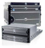
Light, Quantity, Color, Meaning, shows the enclosure address and loop ID indicators
 |
View all Dell DAE2-ATA manuals
Add to My Manuals
Save this manual to your list of manuals |
Page 41 highlights
Servicing a DAE2 Table 3-1 Status Lights Visible from the Front of the Disk Enclosure Light Quantity Color Meaning Disk Enclosure Power 1 Green Power to enclosure is on. Disk Enclosure Fault 1 Amber On when any fault condition exists; if the fault is not obvious from a disk module light, look at the back of the disk enclosure. Disk Active 1 per disk module Green Off when the slot is empty or contains a filler module. Also off when the disk is powered down by command; for example, the result of a temperature fault. Flashing (mostly off) when the FC drive is powered up but not spinning; this is a normal part of the spin-up sequence, occurring during the spin-up delay of a slot. Flashing (at a constant rate) FC drive: when the drive is spinning up or spinning down normally. ATA drive: when the module has received power but the disk has not started spinning On when the drive has power but is not handling any I/O activity (the ready state). ATA modules also show the Disk Active LED on while the disk spins up or down normally. Flashing (mostly on) when the drive is spinning and handling I/O activity. Flashing (constant fast rate) when an ATA LCC has forced ownership of the drive. Disk Fault 1 per disk module Amber On when the disk module is faulty, or as an indication to remove the drive. Figure 3-2 shows the enclosure address and loop ID indicators, visible from the back of the enclosure. Monitoring Disk Enclosure Status 3-3
-
 1
1 -
2
-
3
-
4
-
5
-
6
-
7
-
8
-
9
-
10
-
11
-
12
-
13
-
14
-
15
-
16
-
17
-
18
-
19
-
20
-
21
-
22
-
23
-
24
-
25
-
26
-
27
-
28
-
29
-
30
-
31
-
32
-
33
-
34
-
35
-
 36
36 -
 37
37 -
 38
38 -
 39
39 -
 40
40 -
 41
41 -
 42
42 -
 43
43 -
 44
44 -
 45
45 -
 46
46 -
47
-
48
-
49
-
50
-
51
-
52
-
53
-
54
-
55
-
56
-
57
-
58
-
59
-
60
-
61
-
62
-
63
-
64
-
65
-
66
-
67
-
68
-
69
-
70
-
71
-
72
-
73
-
74
-
75
-
76
-
77
-
78
 |
 |
