Dell Dimension 3100 Owner's Manual - Page 64
Removing the Computer Cover - video card
 |
View all Dell Dimension 3100 manuals
Add to My Manuals
Save this manual to your list of manuals |
Page 64 highlights
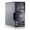
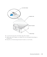
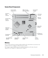
4 network adapter connector To attach your computer to a network or broadband device, connect one end of a network cable to either a network port or your network or broadband device. Connect the other end of the network cable to the network adapter connector on your computer. A click indicates that the network cable has been securely attached. NOTE: Do not plug a telephone cable into the network connector. On computers with a network connector card, use the connector on the card. It is recommended that you use Category 5 wiring and connectors for your network. If you must use Category 3 wiring, force the network speed to 10 Mbps to ensure reliable operation. 5 VGA video connector If your monitor has a VGA connector, plug it into the VGA connector on the computer. 6 card slots Access connectors for any installed PCI cards (two slots) and a x1 PCI Express card. NOTE: Although your computer has 4 card slot openings, it supports a maximum of 3 cards; the bottom slot cannot be used. Removing the Computer Cover CAUTION: Before you begin any of the procedures in this section, follow the safety instructions located in the Product Information Guide. CAUTION: To guard against electrical shock, always unplug your computer from the electrical outlet before removing the cover. 1 Follow the procedures in "Before You Begin" on page 57. NOTICE: Ensure that sufficient space exists to support the removed cover-at least 30 cm (1 ft) of desk top space. NOTICE: Ensure that you are working on a level, protected surface to avoid scratching either the computer or the surface on which it is resting. 2 Lay your computer on its side with the computer cover facing up. 3 Pull back the cover release latch located on the top panel. 62 Removing and Installing Parts
-
 1
1 -
2
-
3
-
4
-
5
-
6
-
7
-
8
-
9
-
10
-
11
-
12
-
13
-
14
-
15
-
16
-
17
-
18
-
19
-
20
-
21
-
22
-
23
-
24
-
25
-
26
-
27
-
28
-
29
-
30
-
31
-
32
-
33
-
34
-
35
-
36
-
37
-
38
-
39
-
40
-
41
-
42
-
43
-
44
-
45
-
46
-
47
-
48
-
49
-
50
-
51
-
52
-
53
-
54
-
55
-
56
-
57
-
58
-
 59
59 -
 60
60 -
 61
61 -
 62
62 -
 63
63 -
 64
64 -
 65
65 -
 66
66 -
 67
67 -
 68
68 -
 69
69 -
70
-
71
-
72
-
73
-
74
-
75
-
76
-
77
-
78
-
79
-
80
-
81
-
82
-
83
-
84
-
85
-
86
-
87
-
88
-
89
-
90
-
91
-
92
-
93
-
94
-
95
-
96
-
97
-
98
-
99
-
100
-
101
-
102
-
103
-
104
-
105
-
106
-
107
-
108
-
109
-
110
-
111
-
112
-
113
-
114
-
115
-
116
-
117
-
118
-
119
-
120
-
121
-
122
-
123
-
124
-
125
-
126
-
127
-
128
-
129
-
130
-
131
-
132
-
133
-
134
-
135
-
136
-
137
-
138
-
139
-
140
 |
 |