Dell Dimension 5100C Owner's Manual - Page 59
Removing the Computer Cover, menu see
 |
View all Dell Dimension 5100C manuals
Add to My Manuals
Save this manual to your list of manuals |
Page 59 highlights
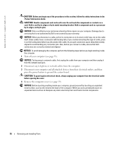
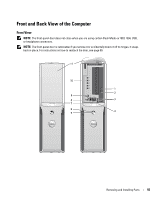
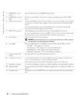
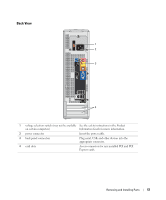
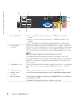
7 line-out connector 8 microphone/side surround sound connector 9 center/LFE connector 10 S/PDIF connector 11 VGA connector 12 USB 2.0 connectors (5) 13 IEEE 1394 connector Use the green line-out connector to attach headphones and most speakers with integrated amplifiers. On computers with a sound card, use the connector on the card. Use the pink and silver connector to attach a personal computer microphone for voice or musical input into a sound or telephony program. On computers with a sound card, the microphone connector is on the card. LFE (Low Frequency Effects) Audio channel found in digital surround sound audio schemes that carries only low frequency information of 80 Hz and below. The LFE channel drives a subwoofer to provide extremely low bass extension. Systems not using subwoofers can shunt the LFE information to the main speakers in the surround sound set-up. This connector is used to transmit digital audio without going through an analog audio conversion process. If your monitor has a VGA connector, plug it into the VGA connector on the computer. Use the back USB connectors for devices that typically remain connected, such as printers and keyboards. It is recommended that you use the front USB connectors for devices that you connect occasionally, such as joysticks or cameras. Attach high-speed serial multimedia devices, such as digital video cameras. Removing the Computer Cover CAUTION: Before you begin any of the procedures in this section, follow the safety instructions in the Product Information Guide. 1 Shut down the computer through the Start menu (see page 53). 2 Ensure that your computer and attached devices are turned off. If your computer and attached devices did not automatically turn off when you shut down your computer, turn them off now. NOTICE: To disconnect a network cable, first unplug the cable from your computer and then unplug it from the network wall jack. 3 Disconnect any telephone or telecommunication lines from the computer. 4 Disconnect your computer and all attached devices from their electrical outlets, and then press the power button to ground the system board. CAUTION: To guard against electrical shock, always unplug your computer from the electrical outlet before opening the cover. NOTICE: Ensure that sufficient space exists to support the removed cover-at least 30 cm (1 ft) of desk top space. Removing and Installing Parts 59
-
 1
1 -
2
-
3
-
4
-
5
-
6
-
7
-
8
-
9
-
10
-
11
-
12
-
13
-
14
-
15
-
16
-
17
-
18
-
19
-
20
-
21
-
22
-
23
-
24
-
25
-
26
-
27
-
28
-
29
-
30
-
31
-
32
-
33
-
34
-
35
-
36
-
37
-
38
-
39
-
40
-
41
-
42
-
43
-
44
-
45
-
46
-
47
-
48
-
49
-
50
-
51
-
52
-
53
-
 54
54 -
 55
55 -
 56
56 -
 57
57 -
 58
58 -
 59
59 -
 60
60 -
 61
61 -
 62
62 -
 63
63 -
 64
64 -
65
-
66
-
67
-
68
-
69
-
70
-
71
-
72
-
73
-
74
-
75
-
76
-
77
-
78
-
79
-
80
-
81
-
82
-
83
-
84
-
85
-
86
-
87
-
88
-
89
-
90
-
91
-
92
-
93
-
94
-
95
-
96
-
97
-
98
-
99
-
100
-
101
-
102
-
103
-
104
-
105
-
106
-
107
-
108
-
109
-
110
-
111
-
112
-
113
-
114
-
115
-
116
-
117
-
118
-
119
-
120
-
121
-
122
-
123
-
124
-
125
-
126
-
127
-
128
 |
 |
