Dell Inspiron 1526 Service Manual - Page 14
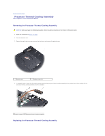
Replacing the Processor Thermal, Cooling Assembly, Back to Contents
 |
View all Dell Inspiron 1526 manuals
Add to My Manuals
Save this manual to your list of manuals |
Page 14 highlights
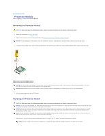
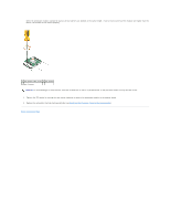
When the processor module is properly seated, all four corners are aligned at the same height. If one or more corners of the module are higher than the others, the module is not seated properly. 1 ZIF-socket cam screw 2 ZIF socket 3 pin-1 corner NOTICE: To avoid damage to the processor, hold the screwdriver so that it is perpendicular to the processor when turning the cam screw. 2. Tighten the ZIF socket by turning the cam screw clockwise to secure the processor module to the system board. 3. Replace the processor thermal-cooling assembly (see Replacing the Processor Thermal-Cooling Assembly). Back to Contents Page
-
 1
1 -
2
-
3
-
4
-
5
-
6
-
7
-
8
-
 9
9 -
 10
10 -
 11
11 -
 12
12 -
 13
13 -
 14
14 -
 15
15 -
 16
16 -
 17
17 -
 18
18 -
 19
19 -
20
-
21
-
22
-
23
-
24
-
25
-
26
-
27
-
28
-
29
-
30
-
31
-
32
-
33
-
34
-
35
-
36
-
37
-
38
-
39
-
40
-
41
-
42
-
43
-
44
-
45
-
46
-
47
-
48
-
49
-
50
-
51
 |
 |

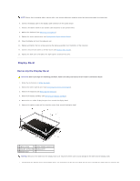
When the processor module is properly seated, all four corners are aligned at the same height. If one or more corners of the module are higher than the
others, the module is not seated properly.
2.
Tighten the ZIF socket by turning the cam screw clockwise to secure the processor module to the system board.
3.
Replace the processor thermal-cooling assembly (see
Replacing the Processor Thermal
-
Cooling Assembly
).
Back to Contents Page
1
ZIF-socket cam screw
2
ZIF socket
3
pin-1 corner
NOTICE:
To avoid damage to the processor, hold the screwdriver so that it is perpendicular to the processor when turning the cam screw.