Dell Inspiron 16 5625 Service Manual - Page 37
Display assembly, Removing the display assembly
 |
View all Dell Inspiron 16 5625 manuals
Add to My Manuals
Save this manual to your list of manuals |
Page 37 highlights
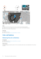
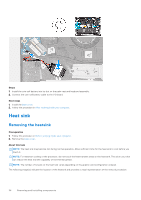
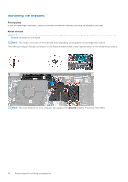
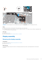
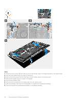
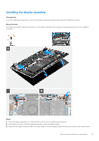
NOTE: This is the heatsink for your computer that supports the integrated Graphics Processing Unit (GPU). Steps 1. Align the screw holes on the heat sink to the screw holes on the system board. 2. In sequential order (1>2>3>4>5>6>7) or (1>2>3>4), tighten the seven or four captive screws, whichever is applicable, that secure the heat sink to the system board. Next steps 1. Install the base cover. 2. Follow the procedure in After working inside your computer. Display assembly Removing the display assembly Prerequisites 1. Follow the procedure in Before working inside your computer. 2. Remove the base cover. About this task The following image(s) indicate the location of the display assembly and provides a visual representation of the removal procedure. Removing and installing components 37
-
 1
1 -
2
-
3
-
4
-
5
-
6
-
7
-
8
-
9
-
10
-
11
-
12
-
13
-
14
-
15
-
16
-
17
-
18
-
19
-
20
-
21
-
22
-
23
-
24
-
25
-
26
-
27
-
28
-
29
-
30
-
31
-
 32
32 -
 33
33 -
 34
34 -
 35
35 -
 36
36 -
 37
37 -
 38
38 -
 39
39 -
 40
40 -
 41
41 -
 42
42 -
43
-
44
-
45
-
46
-
47
-
48
-
49
-
50
-
51
-
52
-
53
-
54
-
55
-
56
-
57
-
58
-
59
-
60
-
61
-
62
-
63
-
64
-
65
-
66
-
67
-
68
-
69
-
70
-
71
-
72
-
73
 |
 |
