Dell Inspiron 16 5625 Service Manual - Page 40
I/O board, Removing the I/O board
 |
View all Dell Inspiron 16 5625 manuals
Add to My Manuals
Save this manual to your list of manuals |
Page 40 highlights
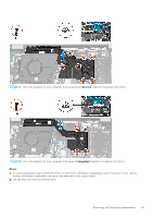
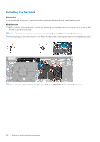
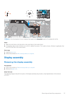
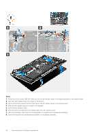
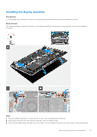
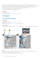
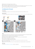
4. Replace the three screws (M2.5x5) that secure the left display hinge to the palm-rest and keyboard assembly. 5. Close the right display hinge and align the screw holes on the right display hinge with the screw holes on the system board. 6. Replace the three screws (M2.5x5) that secure the right display hinge to the palm-rest and keyboard assembly. 7. Replace the display cable to the routing guides on the palm-rest and keyboard assembly. 8. Connect the display cable to the connector on the system board. 9. Close the latch and replace the clear adhesive tape. Next steps 1. Install the base cover. 2. Follow the procedure in After working inside your computer. I/O board Removing the I/O board Prerequisites 1. Follow the procedure in Before working inside your computer. 2. Remove the base cover. 3. Remove the 3-cell battery or 4-cell battery, whichever is applicable. About this task The following image(s) indicate the location of the I/O board and provides a visual representation of the removal procedure. Steps 1. Remove the two screws (M2.5x5) that secure the right-display hinge of the display assembly to the system board. 2. Open the right-display hinge at an angle of 90 degrees. 3. Peel the clear adhesive tape and lift the latch of the I/O-board cable. 40 Removing and installing components
-
 1
1 -
2
-
3
-
4
-
5
-
6
-
7
-
8
-
9
-
10
-
11
-
12
-
13
-
14
-
15
-
16
-
17
-
18
-
19
-
20
-
21
-
22
-
23
-
24
-
25
-
26
-
27
-
28
-
29
-
30
-
31
-
32
-
33
-
34
-
 35
35 -
 36
36 -
 37
37 -
 38
38 -
 39
39 -
 40
40 -
 41
41 -
 42
42 -
 43
43 -
 44
44 -
 45
45 -
46
-
47
-
48
-
49
-
50
-
51
-
52
-
53
-
54
-
55
-
56
-
57
-
58
-
59
-
60
-
61
-
62
-
63
-
64
-
65
-
66
-
67
-
68
-
69
-
70
-
71
-
72
-
73
 |
 |
