Dell Inspiron 17 5767 Inspiron 17 5000 Service Manual - Page 49
Replacing the touch pad, Procedure
 |
View all Dell Inspiron 17 5767 manuals
Add to My Manuals
Save this manual to your list of manuals |
Page 49 highlights
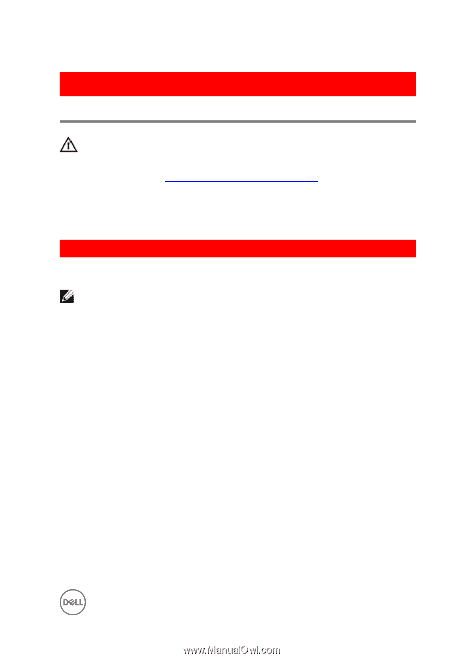
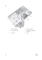
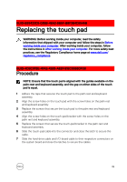
GUID-B55423C5-03BB-46A2-9B5F-B8F3B4C854AB Replacing the touch pad WARNING: Before working inside your computer, read the safety information that shipped with your computer and follow the steps in Before working inside your computer. After working inside your computer, follow the instructions in After working inside your computer. For more safety best practices, see the Regulatory Compliance home page at www.dell.com/ regulatory_compliance. GUID-4DBC978E-4FA2-4265-AE67-91EC5568DF0B Procedure NOTE: Ensure that the touch pad is aligned with the guides available on the palm-rest and keyboard assembly, and the gap on either sides of the touch pad is equal. 1 Adhere the tape that secures the touch pad to the palm rest and keyboard assembly. 2 Align the screw holes on the touch pad with the screw holes on the palm rest and keyboard assembly. 3 Replace the screws that secure the touch pad to the palm rest and keyboard assembly. 4 Align the screw holes on the touch-pad bracket with the screw holes on the palm rest and keyboard assembly. 5 Replace the screws that secure the touch-pad bracket to the palm rest and keyboard assembly. 6 Slide the touch-pad cable into the connector and close the latch to secure the cable. 7 Slide the hard-drive cable and I/O-board cable to their respective connectors on the system board and close the latches to secure the cables. 49
-
 1
1 -
2
-
3
-
4
-
5
-
6
-
7
-
8
-
9
-
10
-
11
-
12
-
13
-
14
-
15
-
16
-
17
-
18
-
19
-
20
-
21
-
22
-
23
-
24
-
25
-
26
-
27
-
28
-
29
-
30
-
31
-
32
-
33
-
34
-
35
-
36
-
37
-
38
-
39
-
40
-
41
-
42
-
43
-
 44
44 -
 45
45 -
 46
46 -
 47
47 -
 48
48 -
 49
49 -
 50
50 -
 51
51 -
 52
52 -
 53
53 -
 54
54 -
55
-
56
-
57
-
58
-
59
-
60
-
61
-
62
-
63
-
64
-
65
-
66
-
67
-
68
-
69
-
70
-
71
-
72
-
73
-
74
-
75
-
76
-
77
-
78
-
79
-
80
-
81
-
82
-
83
-
84
-
85
-
86
-
87
-
88
-
89
-
90
-
91
-
92
-
93
-
94
-
95
-
96
-
97
-
98
-
99
-
100
-
101
-
102
-
103
-
104
-
105
-
106
-
107
-
108
-
109
-
110
-
111
-
112
-
113
-
114
 |
 |