Dell Inspiron 17 5767 Inspiron 17 5000 Service Manual - Page 75
Replacing the system-board assembly, Procedure
 |
View all Dell Inspiron 17 5767 manuals
Add to My Manuals
Save this manual to your list of manuals |
Page 75 highlights
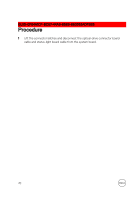
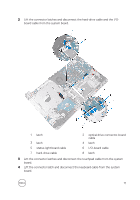
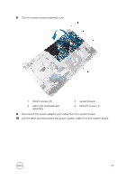
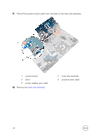
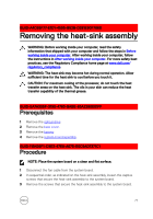
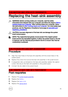
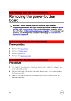
GUID-828BE30D-72EC-4782-A72D-288087A2AB2F Replacing the system-board assembly WARNING: Before working inside your computer, read the safety information that shipped with your computer and follow the steps in Before working inside your computer. After working inside your computer, follow the instructions in After working inside your computer. For more safety best practices, see the Regulatory Compliance home page at www.dell.com/ regulatory_compliance. NOTE: Your computer's Service Tag is stored in the system board. You must enter the Service Tag in the BIOS setup program after you replace the system board. NOTE: Replacing the system board removes any changes you have made to the BIOS using the BIOS setup program. You must make the appropriate changes again after you replace the system board. GUID-42B39242-3113-4AAD-B862-AEDD2053C6F9 Procedure CAUTION: To avoid damaging the system board, ensure that no cables are placed under it. 1 Replace the heat-sink assembly. 2 Connect the power-adapter port cable to the system board. 3 Slide the power-button cable into the connector on system board and press down the latch to secure the cable. 4 Turn the system board assembly over. 5 Slide the ports on the system board assembly into the slots on the palm rest and keyboard assembly. 6 Align the screw holes on the system board assembly with the screw holes on the palm rest and keyboard assembly. 75
-
 1
1 -
2
-
3
-
4
-
5
-
6
-
7
-
8
-
9
-
10
-
11
-
12
-
13
-
14
-
15
-
16
-
17
-
18
-
19
-
20
-
21
-
22
-
23
-
24
-
25
-
26
-
27
-
28
-
29
-
30
-
31
-
32
-
33
-
34
-
35
-
36
-
37
-
38
-
39
-
40
-
41
-
42
-
43
-
44
-
45
-
46
-
47
-
48
-
49
-
50
-
51
-
52
-
53
-
54
-
55
-
56
-
57
-
58
-
59
-
60
-
61
-
62
-
63
-
64
-
65
-
66
-
67
-
68
-
69
-
 70
70 -
 71
71 -
 72
72 -
 73
73 -
 74
74 -
 75
75 -
 76
76 -
 77
77 -
 78
78 -
 79
79 -
 80
80 -
81
-
82
-
83
-
84
-
85
-
86
-
87
-
88
-
89
-
90
-
91
-
92
-
93
-
94
-
95
-
96
-
97
-
98
-
99
-
100
-
101
-
102
-
103
-
104
-
105
-
106
-
107
-
108
-
109
-
110
-
111
-
112
-
113
-
114
 |
 |
