Dell Inspiron 17 7773 2-in-1 Inspiron 17 70002-in-1 Service Manual
Dell Inspiron 17 7773 2-in-1 Manual
 |
View all Dell Inspiron 17 7773 2-in-1 manuals
Add to My Manuals
Save this manual to your list of manuals |
Dell Inspiron 17 7773 2-in-1 manual content summary:
- Dell Inspiron 17 7773 2-in-1 | Inspiron 17 70002-in-1 Service Manual - Page 1
Inspiron 17 7000 2-in-1 Service Manual Computer Model: Inspiron 17-7773 Regulatory Model: P30E Regulatory Type: P30E001 - Dell Inspiron 17 7773 2-in-1 | Inspiron 17 70002-in-1 Service Manual - Page 2
data and tells you how to avoid the problem. WARNING: A WARNING indicates a potential for property damage, personal injury, or death. © 2017-2018 Dell Inc. or its subsidiaries. All rights reserved. Dell, EMC, and other trademarks are trademarks of Dell Inc. or its subsidiaries. Other trademarks may - Dell Inspiron 17 7773 2-in-1 | Inspiron 17 70002-in-1 Service Manual - Page 3
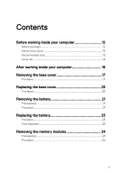
Contents Before working inside your computer 12 Before you begin 12 Safety instructions 12 Recommended tools 13 Screw list 14 After working inside your computer 16 Removing the base cover 17 Procedure 17 Replacing the base cover 20 Procedure 20 Removing the battery 21 Prerequisites 21 - Dell Inspiron 17 7773 2-in-1 | Inspiron 17 70002-in-1 Service Manual - Page 4
Replacing the memory modules 27 Procedure 27 Post-requisites 29 Removing the solid-state drive/Intel Optane memory module 30 Prerequisites 30 Procedure 30 Replacing the solid-state drive/Intel Optane memory module 32 Procedure 32 Post-requisites 33 Removing the hard drive 34 Prerequisites - Dell Inspiron 17 7773 2-in-1 | Inspiron 17 70002-in-1 Service Manual - Page 5
Removing the wireless card 41 Prerequisites 41 Procedure 41 Replacing the wireless card 43 Procedure 43 Post-requisites 44 Removing the speakers 45 Prerequisites 45 Procedure 45 Replacing the speakers 47 Procedure 47 Post-requisites 47 Removing the status-light board 48 Prerequisites - Dell Inspiron 17 7773 2-in-1 | Inspiron 17 70002-in-1 Service Manual - Page 6
Removing the fan 55 Prerequisites 55 Procedure 55 Replacing the fan 57 Procedure 57 Post-requisites 57 Removing the heat sink 58 Prerequisites 58 Procedure 58 Replacing the heat sink 60 Procedure 60 Post-requisites 60 Removing the power-adapter port 61 Prerequisites 61 Procedure 61 - Dell Inspiron 17 7773 2-in-1 | Inspiron 17 70002-in-1 Service Manual - Page 7
78 Post-requisites 78 Removing the system board 79 Prerequisites 79 Procedure 79 Replacing the system board 84 Procedure 84 Post-requisites 85 Entering the Service Tag in the BIOS setup program 85 7 - Dell Inspiron 17 7773 2-in-1 | Inspiron 17 70002-in-1 Service Manual - Page 8
Removing the keyboard 86 Prerequisites 86 Procedure 86 Replacing the keyboard 89 Procedure 89 Post-requisites 89 Removing the palm rest 91 Prerequisites 91 Procedure 92 Replacing the palm rest 93 Procedure 93 Post-requisites 93 Removing the display panel 95 Prerequisites 95 Procedure - Dell Inspiron 17 7773 2-in-1 | Inspiron 17 70002-in-1 Service Manual - Page 9
Replacing the display back-cover and antenna assembly 101 Procedure 101 Post-requisites 101 Removing the camera 102 Prerequisites 102 Procedure 102 Replacing the camera 104 Procedure 104 Post-requisites 104 Removing the sensor board 105 Prerequisites 105 Procedure 105 Replacing the - Dell Inspiron 17 7773 2-in-1 | Inspiron 17 70002-in-1 Service Manual - Page 10
125 Deleting or changing an existing system setup password 125 Clearing CMOS settings 126 Clearing BIOS (System Setup) and System passwords 126 Troubleshooting 127 Flashing the BIOS 127 Flashing BIOS (USB key 127 Enabling Intel Optane memory 128 Disabling Intel Optane memory 128 Enhanced Pre - Dell Inspiron 17 7773 2-in-1 | Inspiron 17 70002-in-1 Service Manual - Page 11
Getting help and contacting Dell 133 Self-help resources 133 Contacting Dell 134 11 - Dell Inspiron 17 7773 2-in-1 | Inspiron 17 70002-in-1 Service Manual - Page 12
card and optical disc from your computer, if applicable. Safety instructions Use the following safety guidelines to protect your computer from potential practices, see the Regulatory Compliance home page at www.dell.com/ regulatory_compliance. WARNING: Disconnect all power sources before opening - Dell Inspiron 17 7773 2-in-1 | Inspiron 17 70002-in-1 Service Manual - Page 13
pins and contacts. CAUTION: You should only perform troubleshooting and repairs as authorized or directed by the Dell technical assistance team. Damage due to servicing that is not authorized by Dell is not covered by your warranty. See the safety instructions that shipped with the product or at www - Dell Inspiron 17 7773 2-in-1 | Inspiron 17 70002-in-1 Service Manual - Page 14
Screw list Table 1. Screw list Component Base cover Secured to Palm-rest assembly Screw type M2.5x8 Quantity Screw image 12 Battery Palm-rest assembly M2x3 4 Solid-state drive Palm-rest assembly M2x3 1 Hard-drive assembly Palm-rest assembly M2x3 3 Hard-drive bracket Hard drive M3x3 4 - Dell Inspiron 17 7773 2-in-1 | Inspiron 17 70002-in-1 Service Manual - Page 15
assembly Palm-rest assembly Palm-rest assembly Display-panel assembly Palm-rest assembly M2.5x6 Big 4 Head M2x2 Big 4 Head M1.2x1.4 20 M2x2 Big 17 Head M2x2 Big 1 Head M2x2 Big 4 Head 15 - Dell Inspiron 17 7773 2-in-1 | Inspiron 17 70002-in-1 Service Manual - Page 16
After working inside your computer CAUTION: Leaving stray or loose screws inside your computer may severely damage your computer. 1 Replace all screws and ensure that no stray screws remain inside your computer. 2 Connect any external devices, peripherals, or cables you removed before working on - Dell Inspiron 17 7773 2-in-1 | Inspiron 17 70002-in-1 Service Manual - Page 17
the safety information that shipped with your computer and follow the steps in Before working inside your computer. After working inside your computer, follow the instructions in After working inside your computer. For more safety best practices, see the Regulatory Compliance home page at www - Dell Inspiron 17 7773 2-in-1 | Inspiron 17 70002-in-1 Service Manual - Page 18
2 Remove the 12 screws (M2.5x8) that secure the base cover to the palm-rest assembly. Figure 1. Removing the screws 1 screws (12) 2 base cover 18 - Dell Inspiron 17 7773 2-in-1 | Inspiron 17 70002-in-1 Service Manual - Page 19
3 Using your fingertips, pry the base cover off the palm-rest assembly. Figure 2. Removing the base cover 1 palm-rest assembly 2 base cover 19 - Dell Inspiron 17 7773 2-in-1 | Inspiron 17 70002-in-1 Service Manual - Page 20
your computer. After working inside your computer, follow the instructions in After working inside your computer. For more safety best practices, see the Regulatory Compliance home page at www.dell.com/ regulatory_compliance. Procedure 1 Align the base cover with the palm-rest - Dell Inspiron 17 7773 2-in-1 | Inspiron 17 70002-in-1 Service Manual - Page 21
your computer. After working inside your computer, follow the instructions in After working inside your computer. For more safety best practices, see the Regulatory Compliance home page at www.dell.com/ regulatory_compliance. Prerequisites Remove the base cover. Procedure 1 - Dell Inspiron 17 7773 2-in-1 | Inspiron 17 70002-in-1 Service Manual - Page 22
3 Lift the battery off the palm-rest assembly. Figure 3. Removing the battery 1 battery cable 3 battery 2 screws (4) 4 palm-rest assembly 4 Press and hold the power button for five seconds to ground the system board. 22 - Dell Inspiron 17 7773 2-in-1 | Inspiron 17 70002-in-1 Service Manual - Page 23
your computer. After working inside your computer, follow the instructions in After working inside your computer. For more safety best practices , see the Regulatory Compliance home page at www.dell.com/ regulatory_compliance. Procedure 1 Align the screw holes on the battery with - Dell Inspiron 17 7773 2-in-1 | Inspiron 17 70002-in-1 Service Manual - Page 24
the safety information that shipped with your computer and follow the steps in Before working inside your computer. After working inside your computer, follow the instructions in After working inside your computer. For more safety best practices, see the Regulatory Compliance home page at www - Dell Inspiron 17 7773 2-in-1 | Inspiron 17 70002-in-1 Service Manual - Page 25
Procedure 1 Lift the Mylar to access the memory module. Figure 4. Lifting the Mylar 1 memory module 2 Mylar 2 Use your fingertips to carefully spread apart the securing-clips on each end of the memory-module slot until the memory module pops up. 25 - Dell Inspiron 17 7773 2-in-1 | Inspiron 17 70002-in-1 Service Manual - Page 26
3 Slide and remove the memory module from the memory-module slot. Figure 5. Removing the memory module 1 securing clips (2) 3 memory-module slot 2 memory module 26 - Dell Inspiron 17 7773 2-in-1 | Inspiron 17 70002-in-1 Service Manual - Page 27
your computer. After working inside your computer, follow the instructions in After working inside your computer. For more safety best practices, see the Regulatory Compliance home page at www.dell.com/ regulatory_compliance. Procedure 1 Lift the Mylar to access the memory- - Dell Inspiron 17 7773 2-in-1 | Inspiron 17 70002-in-1 Service Manual - Page 28
3 Slide the memory module firmly into the slot at an angle and press the memory module down until it clicks into place. NOTE: If you do not hear the click, remove the memory module and reinstall it. Figure 6. Replacing the memory module 1 memory module 3 notch 5 Mylar 2 memory-module slot 4 tab - Dell Inspiron 17 7773 2-in-1 | Inspiron 17 70002-in-1 Service Manual - Page 29
Post-requisites 1 Replace the battery. 2 Replace the base cover. 29 - Dell Inspiron 17 7773 2-in-1 | Inspiron 17 70002-in-1 Service Manual - Page 30
your computer. After working inside your computer, follow the instructions in After working inside your computer. For more safety best practices, see the Regulatory Compliance home page at www.dell.com/ regulatory_compliance. Prerequisites 1 Remove the base cover. 2 Remove the - Dell Inspiron 17 7773 2-in-1 | Inspiron 17 70002-in-1 Service Manual - Page 31
2 Slide and remove the solid-state drive from the solid-state drive slot. Figure 7. Removing the solid-state drive 1 screw 3 solid-state drive slot 2 solid-state drive 31 - Dell Inspiron 17 7773 2-in-1 | Inspiron 17 70002-in-1 Service Manual - Page 32
your computer. After working inside your computer, follow the instructions in After working inside your computer. For more safety best practices, see the Regulatory Compliance home page at www.dell.com/ regulatory_compliance. CAUTION: Solid-state drives are fragile. Exercise care - Dell Inspiron 17 7773 2-in-1 | Inspiron 17 70002-in-1 Service Manual - Page 33
3 Press the other end of the solid-state drive and replace the screw (M2x3) that secures the solid-state drive to the palm-rest assembly. Figure 8. Replacing the solid-state drive 1 screw 3 tab 5 solid-state drive slot Post-requisites 1 Replace the battery. 2 Replace the base cover. 2 notch 4 - Dell Inspiron 17 7773 2-in-1 | Inspiron 17 70002-in-1 Service Manual - Page 34
your computer. After working inside your computer, follow the instructions in After working inside your computer. For more safety best practices, see the Regulatory Compliance home page at www.dell.com/ regulatory_compliance. CAUTION: Hard drives are fragile. Exercise care when - Dell Inspiron 17 7773 2-in-1 | Inspiron 17 70002-in-1 Service Manual - Page 35
3 Lift the hard-drive assembly, along with its cable, off the palm-rest assembly. Figure 9. Removing the hard-drive assembly 1 screws (3) 3 palm-rest assembly 5 pull tab 2 hard-drive assembly 4 hard-drive cable 35 - Dell Inspiron 17 7773 2-in-1 | Inspiron 17 70002-in-1 Service Manual - Page 36
4 Disconnect the interposer from the hard-drive assembly. Figure 10. Removing the interposer 1 hard-drive assembly 2 interposer 5 Remove the four screws (M3x3) that secure the hard-drive bracket to the hard drive. 6 Lift the hard-drive bracket off the hard drive. Figure 11. Removing the hard- - Dell Inspiron 17 7773 2-in-1 | Inspiron 17 70002-in-1 Service Manual - Page 37
your computer. After working inside your computer, follow the instructions in After working inside your computer. For more safety best practices, see the Regulatory Compliance home page at www.dell.com/ regulatory_compliance. CAUTION: Hard drives are fragile. Exercise care when - Dell Inspiron 17 7773 2-in-1 | Inspiron 17 70002-in-1 Service Manual - Page 38
your computer. After working inside your computer, follow the instructions in After working inside your computer. For more safety best practices, see the Regulatory Compliance home page at www.dell.com/ regulatory_compliance. CAUTION: Removing the coin-cell battery resets the - Dell Inspiron 17 7773 2-in-1 | Inspiron 17 70002-in-1 Service Manual - Page 39
2 Peel the coin-cell battery off the palm-rest assembly. Figure 12. Removing the coin-cell battery 1 coin-cell battery cable 3 I/O board 2 coin-cell battery 4 palm-rest assembly 39 - Dell Inspiron 17 7773 2-in-1 | Inspiron 17 70002-in-1 Service Manual - Page 40
your computer. After working inside your computer, follow the instructions in After working inside your computer. For more safety best practices, see the Regulatory Compliance home page at www.dell.com/ regulatory_compliance. Procedure 1 Adhere the coin-cell battery to the - Dell Inspiron 17 7773 2-in-1 | Inspiron 17 70002-in-1 Service Manual - Page 41
your computer. After working inside your computer, follow the instructions in After working inside your computer. For more safety best practices, see the Regulatory Compliance home page at www.dell.com/ regulatory_compliance. Prerequisites 1 Remove the base cover. 2 Remove - Dell Inspiron 17 7773 2-in-1 | Inspiron 17 70002-in-1 Service Manual - Page 42
3 Slide and remove the wireless card from the wireless-card slot. Figure 13. Removing the wireless card 1 screw 3 wireless-card slot 5 antenna cables (2) 2 wireless-card bracket 4 wireless card 42 - Dell Inspiron 17 7773 2-in-1 | Inspiron 17 70002-in-1 Service Manual - Page 43
inside your computer, follow the instructions in After working inside your computer. For see the Regulatory Compliance home page at www.dell.com/ regulatory_compliance. Procedure CAUTION: To avoid antenna-cable color scheme for the wireless card supported by your computer. Table 2. Antenna-cable - Dell Inspiron 17 7773 2-in-1 | Inspiron 17 70002-in-1 Service Manual - Page 44
5 Replace the screw (M2x3) that secures the wireless-card bracket to the wireless card and palm-rest assembly. Figure 14. Replacing the wireless card 1 tab 3 wireless-card slot 5 antenna cables (2) 7 screw Post-requisites 1 Replace the battery. 2 Replace the base cover. 2 notch 4 wireless card 6 - Dell Inspiron 17 7773 2-in-1 | Inspiron 17 70002-in-1 Service Manual - Page 45
inside your computer. After working inside your computer, follow the instructions in After working inside your computer. For more safety best practices, see the Regulatory Compliance home page at www.dell.com/ regulatory_compliance. Prerequisites 1 Remove the base cover. 2 Remove - Dell Inspiron 17 7773 2-in-1 | Inspiron 17 70002-in-1 Service Manual - Page 46
3 Remove the speakers from the alignment posts and lift the speakers off the palm-rest assembly. Figure 15. Removing the speakers 1 speaker cable 3 palm-rest assembly 5 speakers (2) 2 routing guides (2) 4 alignment posts (4) 46 - Dell Inspiron 17 7773 2-in-1 | Inspiron 17 70002-in-1 Service Manual - Page 47
inside your computer, follow the instructions in After working inside your computer. the Regulatory Compliance home page at www.dell.com/ regulatory_compliance. Procedure 1 Using the rest assembly. 2 Route the speaker cable through the routing guides on the palm-rest assembly. 3 Connect the speaker cable - Dell Inspiron 17 7773 2-in-1 | Inspiron 17 70002-in-1 Service Manual - Page 48
inside your computer, follow the instructions in After working inside your computer. For the Regulatory Compliance home page at www.dell.com/ regulatory_compliance. Prerequisites 1 Remove the 2 Remove the speaker cable from the routing guides on the palm-rest assembly. 3 Peel off the foam that - Dell Inspiron 17 7773 2-in-1 | Inspiron 17 70002-in-1 Service Manual - Page 49
4 Lift the status-light board off the palm-rest assembly. Figure 16. Removing the status-light board 1 latch 3 status-light board 5 routing guides (2) 2 status-light board cable 4 foam 6 speaker cable 49 - Dell Inspiron 17 7773 2-in-1 | Inspiron 17 70002-in-1 Service Manual - Page 50
working inside your computer, follow the instructions in After working inside your computer. For more practices, see the Regulatory Compliance home page at www.dell.com/ regulatory_compliance. Procedure 1 Place the status-light routing guides on the palm-rest assembly. Post-requisites 1 Replace the battery. - Dell Inspiron 17 7773 2-in-1 | Inspiron 17 70002-in-1 Service Manual - Page 51
inside your computer. After working inside your computer, follow the instructions in After working inside your computer. For more safety best practices, see the Regulatory Compliance home page at www.dell.com/ regulatory_compliance. Prerequisites 1 Remove the base cover. 2 Remove - Dell Inspiron 17 7773 2-in-1 | Inspiron 17 70002-in-1 Service Manual - Page 52
3 Peel off the tapes that secure the touch-pad assembly to the palm-rest assembly. Figure 17. Removing the touch pad cable 1 latch 3 tapes (2) 2 status-light cable 4 Open the latches, and then disconnect the touch-pad cable from the system board and - Dell Inspiron 17 7773 2-in-1 | Inspiron 17 70002-in-1 Service Manual - Page 53
6 Lift the touchpad off the palm-rest assembly. Figure 18. Removing the touchpad 1 latch 3 screws (4) 2 touch-pad cable 4 touchpad 53 - Dell Inspiron 17 7773 2-in-1 | Inspiron 17 70002-in-1 Service Manual - Page 54
your computer. After working inside your computer, follow the instructions in After working inside your computer. For more safety best practices, see the Regulatory Compliance home page at www.dell.com/ regulatory_compliance. Procedure 1 Align the screw holes on the touch pad - Dell Inspiron 17 7773 2-in-1 | Inspiron 17 70002-in-1 Service Manual - Page 55
your computer. After working inside your computer, follow the instructions in After working inside your computer. For more safety best practices, see the Regulatory Compliance home page at www.dell.com/ regulatory_compliance. Prerequisites 1 Remove the base cover. 2 Remove the - Dell Inspiron 17 7773 2-in-1 | Inspiron 17 70002-in-1 Service Manual - Page 56
4 Lift the fan off the palm-rest assembly. Figure 19. Removing the fan 1 screws (2) 3 tape 2 fan 4 fan cable 56 - Dell Inspiron 17 7773 2-in-1 | Inspiron 17 70002-in-1 Service Manual - Page 57
your computer. After working inside your computer, follow the instructions in After working inside your computer. For more safety best practices, see the Regulatory Compliance home page at www.dell.com/ regulatory_compliance. Procedure 1 Align the screw holes on the fan with - Dell Inspiron 17 7773 2-in-1 | Inspiron 17 70002-in-1 Service Manual - Page 58
inside your computer. After working inside your computer, follow the instructions in After working inside your computer. For more safety best practices, see the Regulatory Compliance home page at www.dell.com/ regulatory_compliance. WARNING: The heat sink may become hot during - Dell Inspiron 17 7773 2-in-1 | Inspiron 17 70002-in-1 Service Manual - Page 59
2 Lift the heat sink off the system board. Figure 20. Removing the heat sink 1 heat sink 3 system board 2 captive screws (7) 59 - Dell Inspiron 17 7773 2-in-1 | Inspiron 17 70002-in-1 Service Manual - Page 60
your computer. After working inside your computer, follow the instructions in After working inside your computer. For more safety best practices, see the Regulatory Compliance home page at www.dell.com/ regulatory_compliance. CAUTION: Incorrect alignment of the heat sink can - Dell Inspiron 17 7773 2-in-1 | Inspiron 17 70002-in-1 Service Manual - Page 61
your computer. After working inside your computer, follow the instructions in After working inside your computer. For more safety best practices, see the Regulatory Compliance home page at www.dell.com/ regulatory_compliance. Prerequisites 1 Remove the base cover. 2 Remove the - Dell Inspiron 17 7773 2-in-1 | Inspiron 17 70002-in-1 Service Manual - Page 62
3 Lift the power-adapter port off the palm-rest assembly. Figure 21. Removing the power-adapter port 1 power-adapter port cable 3 power-adapter port 2 screw 4 palm-rest assembly 62 - Dell Inspiron 17 7773 2-in-1 | Inspiron 17 70002-in-1 Service Manual - Page 63
your computer. After working inside your computer, follow the instructions in After working inside your computer. For more safety best practices, see the Regulatory Compliance home page at www.dell.com/ regulatory_compliance. Procedure 1 Place the power-adapter port into the - Dell Inspiron 17 7773 2-in-1 | Inspiron 17 70002-in-1 Service Manual - Page 64
inside your computer, follow the instructions in After working inside your computer. the Regulatory Compliance home page at www.dell.com/ regulatory_compliance. Prerequisites 1 Remove the the power and volume-buttons board cable from the routing guides on the palm-rest assembly. 4 Remove the screw ( - Dell Inspiron 17 7773 2-in-1 | Inspiron 17 70002-in-1 Service Manual - Page 65
5 Lift the power and volume-buttons board off the palm-rest assembly. Figure 22. Removing the power and volume-buttons board 1 power and volume-buttons board cable 3 screw 5 palm-rest assembly 2 tape 4 power and volume-buttons board 6 routing guides (2) 65 - Dell Inspiron 17 7773 2-in-1 | Inspiron 17 70002-in-1 Service Manual - Page 66
inside your computer, follow the instructions in After working inside your computer. the Regulatory Compliance home page at www.dell.com/ regulatory_compliance. Procedure 1 Align the the power and volume-buttons board cable through the routing guides on the palm-rest assembly. 4 Connect the power and - Dell Inspiron 17 7773 2-in-1 | Inspiron 17 70002-in-1 Service Manual - Page 67
your computer. After working inside your computer, follow the instructions in After working inside your computer. For more safety best practices , see the Regulatory Compliance home page at www.dell.com/ regulatory_compliance. Prerequisites 1 Remove the base cover. 2 Remove the - Dell Inspiron 17 7773 2-in-1 | Inspiron 17 70002-in-1 Service Manual - Page 68
2 Lift the graphics daughter-board brackets off the palm-rest assembly. Figure 23. Removing the graphics daughter-board brackets 1 screws (4) 3 system board 2 graphics daughter-board brackets (2) 4 palm-rest assembly 3 Remove the two screws (M2x2 Big Head) that secure the graphics daughterboard - Dell Inspiron 17 7773 2-in-1 | Inspiron 17 70002-in-1 Service Manual - Page 69
4 Lift the graphics daughter-board off the palm-rest assembly. Figure 24. Removing the graphics daughter-board 1 graphics daughter-board 3 palm-rest assembly 2 screws (2) 69 - Dell Inspiron 17 7773 2-in-1 | Inspiron 17 70002-in-1 Service Manual - Page 70
your computer. After working inside your computer, follow the instructions in After working inside your computer. For more safety best practices, see the Regulatory Compliance home page at www.dell.com/ regulatory_compliance. Procedure 1 Align the screw holes on the graphics - Dell Inspiron 17 7773 2-in-1 | Inspiron 17 70002-in-1 Service Manual - Page 71
your computer. After working inside your computer, follow the instructions in After working inside your computer. For more safety best practices, see the Regulatory Compliance home page at www.dell.com/ regulatory_compliance. Prerequisites 1 Remove the base cover. 2 Remove the - Dell Inspiron 17 7773 2-in-1 | Inspiron 17 70002-in-1 Service Manual - Page 72
6 Lift the I/O board off the palm-rest assembly. Figure 25. Removing the I/O board 1 I/O board 3 I/O-board cable 5 palm-rest assembly 7 coin-cell battery cable 2 tape 4 screw 6 latch 8 power and volume-buttons board cable 72 - Dell Inspiron 17 7773 2-in-1 | Inspiron 17 70002-in-1 Service Manual - Page 73
your computer. After working inside your computer, follow the instructions in After working inside your computer. For more safety best practices , see the Regulatory Compliance home page at www.dell.com/ regulatory_compliance. Procedure 1 Using the alignment posts, place the I/O - Dell Inspiron 17 7773 2-in-1 | Inspiron 17 70002-in-1 Service Manual - Page 74
your computer. After working inside your computer, follow the instructions in After working inside your computer. For more safety best practices, see the Regulatory Compliance home page at www.dell.com/ regulatory_compliance. Prerequisites 1 Remove the base cover. 2 Remove the - Dell Inspiron 17 7773 2-in-1 | Inspiron 17 70002-in-1 Service Manual - Page 75
4 Peel off the display cable and the touch-screen board cable from the system board. Figure 26. Disconnecting the cables 1 antenna cables (2) 3 palm-rest assembly 5 display cable 7 latches (2) 2 tape 4 touch-screen board cable 6 tapes (2) 5 Turn the computer over and open the display as far as - Dell Inspiron 17 7773 2-in-1 | Inspiron 17 70002-in-1 Service Manual - Page 76
7 Remove the four screws (M2.5x6 Big Head) that secure the display assembly to the palm-rest assembly. Figure 27. Removing the display assembly 1 display assembly 3 display hinges (2) 2 screws (4) 4 palm-rest assembly 76 - Dell Inspiron 17 7773 2-in-1 | Inspiron 17 70002-in-1 Service Manual - Page 77
8 Lift the display assembly off the palm-rest assembly. Figure 28. Display assembly 1 display assembly 77 - Dell Inspiron 17 7773 2-in-1 | Inspiron 17 70002-in-1 Service Manual - Page 78
your computer. After working inside your computer, follow the instructions in After working inside your computer. For more safety best practices, see the Regulatory Compliance home page at www.dell.com/ regulatory_compliance. Procedure CAUTION: Place the computer on a soft - Dell Inspiron 17 7773 2-in-1 | Inspiron 17 70002-in-1 Service Manual - Page 79
your computer. After working inside your computer, follow the instructions in After working inside your computer. For more safety best practices, see the Regulatory Compliance home page at www.dell.com/ regulatory_compliance. NOTE: Your computer's Service Tag is stored in the system board. You must - Dell Inspiron 17 7773 2-in-1 | Inspiron 17 70002-in-1 Service Manual - Page 80
4 Peel off the tape that secures the I/O-board cable to the system board. 5 Open the latch and disconnect the I/O-board cable from the system board. Figure 29. Disconnecting the cables 6 Using the pull tab, disconnect the hard-drive cable from the system board. 7 Disconnect the power-adapter cable - Dell Inspiron 17 7773 2-in-1 | Inspiron 17 70002-in-1 Service Manual - Page 81
9 Open the latch and disconnect the status-light board cable, keyboard cable, keyboard-backlight cable, and touch pad cable from the system board. Figure 30. Disconnecting the cables 1 hard-drive cable 3 speaker cable 5 status-light board cable 7 keyboard-backlight cable 2 power-adapter port - Dell Inspiron 17 7773 2-in-1 | Inspiron 17 70002-in-1 Service Manual - Page 82
11 Remove the two screws (M2x3) that secure the USB Type-C bracket to the system board and the palm-rest assembly. Figure 31. Removing the brackets 1 screws (6) 3 USB Type-C bracket 2 graphics daughter-board brackets 12 Remove the four screws (M2x2 Big Head) that secure the system board to the - Dell Inspiron 17 7773 2-in-1 | Inspiron 17 70002-in-1 Service Manual - Page 83
13 Lift the system board off the palm-rest assembly. Figure 32. Removing the system board 1 screws (4) 3 palm-rest assembly 2 system board 83 - Dell Inspiron 17 7773 2-in-1 | Inspiron 17 70002-in-1 Service Manual - Page 84
your computer. After working inside your computer, follow the instructions in After working inside your computer. For more safety best practices, see the Regulatory Compliance home page at www.dell.com/ regulatory_compliance. NOTE: Your computer's Service Tag is stored in the system board. You must - Dell Inspiron 17 7773 2-in-1 | Inspiron 17 70002-in-1 Service Manual - Page 85
the heat sink. 3 Replace the memory modules. 4 Replace the battery. 5 Replace the base cover. Entering the Service Tag in the BIOS setup program 1 Turn on or restart your computer. 2 Press F2 when the Dell logo is displayed to enter the BIOS setup program. 3 Navigate to the Main tab and enter the - Dell Inspiron 17 7773 2-in-1 | Inspiron 17 70002-in-1 Service Manual - Page 86
your computer, follow the instructions in After working inside your computer. the Regulatory Compliance home page at www.dell.com/ regulatory_compliance. Prerequisites 1 Remove the port. 12 Remove the system board. Procedure 1 Remove the 17 screws (M2x2 Big Head) that secure the keyboard bracket to - Dell Inspiron 17 7773 2-in-1 | Inspiron 17 70002-in-1 Service Manual - Page 87
3 Lift the keyboard bracket off the palm-rest assembly. Figure 33. Removing the keyboard bracket 1 keyboard bracket 3 screws (17) 2 palm-rest assembly 4 tape 4 Remove the 18 screws (M1.2x1.4) that secure the keyboard to the palm-rest assembly. 87 - Dell Inspiron 17 7773 2-in-1 | Inspiron 17 70002-in-1 Service Manual - Page 88
5 Lift the keyboard off the palm-rest assembly. Figure 34. Removing the keyboard 1 keyboard 3 screws (18) 2 palm-rest assembly 88 - Dell Inspiron 17 7773 2-in-1 | Inspiron 17 70002-in-1 Service Manual - Page 89
inside your computer, follow the instructions in After working inside your computer. see the Regulatory Compliance home page at www.dell.com/ regulatory_compliance. Procedure 1 Align the screw holes on the palm-rest assembly. 4 Replace the 17 screws (M2x2 Big Head) that secure the keyboard bracket to - Dell Inspiron 17 7773 2-in-1 | Inspiron 17 70002-in-1 Service Manual - Page 90
12 Replace the base cover. 90 - Dell Inspiron 17 7773 2-in-1 | Inspiron 17 70002-in-1 Service Manual - Page 91
working inside your computer, follow the instructions in After working inside your computer. For , see the Regulatory Compliance home page at www.dell.com/ regulatory_compliance. Prerequisites 1 Remove the base cover power-adapter port. 17 Remove the power and volume-buttons board. 18 Remove the speakers. - Dell Inspiron 17 7773 2-in-1 | Inspiron 17 70002-in-1 Service Manual - Page 92
Procedure After performing the steps in prerequisites we are left with the palm rest. Figure 35. Removing the palm rest 1 palm rest 92 - Dell Inspiron 17 7773 2-in-1 | Inspiron 17 70002-in-1 Service Manual - Page 93
After working inside your computer, follow the instructions in After working inside your computer. For more safety best practices, see the Regulatory Compliance home page at www.dell.com/ regulatory_compliance. Procedure Place the palm rest on a 17 Replace the memory modules. 18 Replace the battery. 93 - Dell Inspiron 17 7773 2-in-1 | Inspiron 17 70002-in-1 Service Manual - Page 94
19 Replace the base cover. 94 - Dell Inspiron 17 7773 2-in-1 | Inspiron 17 70002-in-1 Service Manual - Page 95
inside your computer, follow the instructions in After working inside your computer. the Regulatory Compliance home page at www.dell.com/ regulatory_compliance. Prerequisites 1 Remove the . Procedure 1 Remove the display cable from the routing guide inside the hinge cover. 2 Using a plastic scribe, - Dell Inspiron 17 7773 2-in-1 | Inspiron 17 70002-in-1 Service Manual - Page 96
3 Lift the display-panel assembly off the display back-cover and antenna assembly. Figure 36. Removing the display-panel assembly 1 plastic scribe 3 display-panel assembly 2 display back-cover and antenna assembly 4 display cable CAUTION: Place the display-panel assembly on a soft and clean - Dell Inspiron 17 7773 2-in-1 | Inspiron 17 70002-in-1 Service Manual - Page 97
7 Remove the display cable. After performing the above steps, we are left with the display panel. Figure 37. Display panel 1 display panel 97 - Dell Inspiron 17 7773 2-in-1 | Inspiron 17 70002-in-1 Service Manual - Page 98
your computer, follow the instructions in After working inside your computer. see the Regulatory Compliance home page at www.dell.com/ regulatory_compliance. Procedure 1 Place the display assembly over. 6 Route the display cable through the routing guide inside the hinge cover. 7 Align the tabs on - Dell Inspiron 17 7773 2-in-1 | Inspiron 17 70002-in-1 Service Manual - Page 99
your computer. After working inside your computer, follow the instructions in After working inside your computer. For more safety best practices, see the Regulatory Compliance home page at www.dell.com/ regulatory_compliance. Prerequisites 1 Remove the base cover. 2 Remove the - Dell Inspiron 17 7773 2-in-1 | Inspiron 17 70002-in-1 Service Manual - Page 100
Figure 38. Display back-cover and antenna assembly 1 display back-cover and antenna assembly 100 - Dell Inspiron 17 7773 2-in-1 | Inspiron 17 70002-in-1 Service Manual - Page 101
your computer. After working inside your computer, follow the instructions in After working inside your computer. For more safety best practices, see the Regulatory Compliance home page at www.dell.com/ regulatory_compliance. Procedure Place the display back-cover and antenna - Dell Inspiron 17 7773 2-in-1 | Inspiron 17 70002-in-1 Service Manual - Page 102
your computer. After working inside your computer, follow the instructions in After working inside your computer. For more safety best practices, see the Regulatory Compliance home page at www.dell.com/ regulatory_compliance. Prerequisites 1 Remove the base cover. 2 Remove the - Dell Inspiron 17 7773 2-in-1 | Inspiron 17 70002-in-1 Service Manual - Page 103
3 Disconnect the camera cable from the camera module. Figure 39. Removing the camera 1 display-panel assembly 3 camera module 2 plastic scribe 4 camera cable 103 - Dell Inspiron 17 7773 2-in-1 | Inspiron 17 70002-in-1 Service Manual - Page 104
your computer. After working inside your computer, follow the instructions in After working inside your computer. For more safety best practices, see the Regulatory Compliance home page at www.dell.com/ regulatory_compliance. Procedure 1 Connect the camera cable to the camera - Dell Inspiron 17 7773 2-in-1 | Inspiron 17 70002-in-1 Service Manual - Page 105
your computer. After working inside your computer, follow the instructions in After working inside your computer. For more safety best practices, see the Regulatory Compliance home page at www.dell.com/ regulatory_compliance. Prerequisites 1 Remove the base cover. 2 Remove the - Dell Inspiron 17 7773 2-in-1 | Inspiron 17 70002-in-1 Service Manual - Page 106
4 Lift the sensor board off the display-panel assembly. Figure 40. Removing the sensor-board cable 1 sensor board 3 tape 5 latch 2 screw 4 sensor-board cable 106 - Dell Inspiron 17 7773 2-in-1 | Inspiron 17 70002-in-1 Service Manual - Page 107
your computer. After working inside your computer, follow the instructions in After working inside your computer. For more safety best practices, see the Regulatory Compliance home page at www.dell.com/ regulatory_compliance. Procedure 1 Align the sensor board on the display- - Dell Inspiron 17 7773 2-in-1 | Inspiron 17 70002-in-1 Service Manual - Page 108
your computer. After working inside your computer, follow the instructions in After working inside your computer. For more safety best practices, see the Regulatory Compliance home page at www.dell.com/ regulatory_compliance. Prerequisites 1 Remove the base cover. 2 Remove the - Dell Inspiron 17 7773 2-in-1 | Inspiron 17 70002-in-1 Service Manual - Page 109
3 Lift the display cable off the display-panel assembly. Figure 41. Removing the display cable 1 display-panel assembly 3 display cables (2) 2 latches (2) 4 tapes (2) 109 - Dell Inspiron 17 7773 2-in-1 | Inspiron 17 70002-in-1 Service Manual - Page 110
inside your computer. After working inside your computer, follow the instructions in After working inside your computer. For more safety best practices, see the Regulatory Compliance home page at www.dell.com/ regulatory_compliance. Procedure 1 Slide the display cable into their - Dell Inspiron 17 7773 2-in-1 | Inspiron 17 70002-in-1 Service Manual - Page 111
or double-tap the audio driver file icon and follow the instructions on the screen to install the driver. Downloading the graphics driver 1 Turn on your computer. 2 Go to www.dell.com/support. 3 Click or tap Product support enter the Service Tag of your computer, and then click or tap Submit. NOTE - Dell Inspiron 17 7773 2-in-1 | Inspiron 17 70002-in-1 Service Manual - Page 112
driver file. 8 Double-click or double-tap the driver file icon and follow the instructions on screen. Downloading the Wi-Fi driver 1 Turn on your computer. 2 Go to www.dell.com/support. 3 Click or tap Product support enter the Service Tag of your computer, and then click or tap Submit. NOTE: If you - Dell Inspiron 17 7773 2-in-1 | Inspiron 17 70002-in-1 Service Manual - Page 113
file. 8 Double-click the card reader driver file icon, and follow the instructions on the screen. Downloading the chipset driver 1 Turn on your computer. 2 Go to www.dell.com/support. 3 Click or tap Product support, enter the Service Tag of your computer, and then click or tap Submit. NOTE: If you - Dell Inspiron 17 7773 2-in-1 | Inspiron 17 70002-in-1 Service Manual - Page 114
3 Click Product support enter the Service Tag of your computer and click Submit. NOTE: If you do not have the Service Tag, use the auto-detect feature or manually browse for your computer model. 4 Click Drivers & 8 Double-click the network driver file icon and follow the instructions on screen. 114 - Dell Inspiron 17 7773 2-in-1 | Inspiron 17 70002-in-1 Service Manual - Page 115
boot device order and boot directly to a specific device (for example: optical drive or hard drive). During the Power-on Self Test (POST), when the Dell logo appears, you can: • Access System Setup by pressing F2 key • Bring up the one-time boot menu by pressing F12 key The one-time - Dell Inspiron 17 7773 2-in-1 | Inspiron 17 70002-in-1 Service Manual - Page 116
Keys Up arrow Down arrow Enter Spacebar Tab Navigation Moves to the previous field. Moves to the next field. Selects a value in the selected field (if applicable) or follow the link in the field. Expands or collapses a drop‐down list, if applicable. Moves to the next focus area. NOTE: For the - Dell Inspiron 17 7773 2-in-1 | Inspiron 17 70002-in-1 Service Manual - Page 117
2 During POST, when the DELL logo is displayed, watch for the F2 prompt to appear, and then press General-System Information System Information BIOS Version Displays the BIOS version number. Service Tag Displays the Service Tag of the computer. Asset Tag Displays the Asset Tag of the - Dell Inspiron 17 7773 2-in-1 | Inspiron 17 70002-in-1 Service Manual - Page 118
General-System Information Processor Information Processor Type Displays the processor type. Core Count Displays the number of cores on the processor. Processor ID Displays the processor identification code. Current Clock Speed Displays the current processor clock speed. Minimum Clock - Dell Inspiron 17 7773 2-in-1 | Inspiron 17 70002-in-1 Service Manual - Page 119
controller. Drives Enable or disable various drives on board. SMART Reporting Enable or disable SMART Reporting during system startup. USB Configuration Enable Boot Support Enable or disable booting from USB mass storage devices such as external hard drive, optical drive, and USB drive. 119 - Dell Inspiron 17 7773 2-in-1 | Inspiron 17 70002-in-1 Service Manual - Page 120
System Configuration Enable External USB Port Enable or disable booting from USB mass storage devices connected to external USB port. USB PowerShare Enable or disable charging external devices through the USB PowerShare port. Audio Enable or disable the integrated audio controller. Keyboard - Dell Inspiron 17 7773 2-in-1 | Inspiron 17 70002-in-1 Service Manual - Page 121
PTT) visibility to the operating system. Computrace(R) Enable or disable the BIOS module interface of the optional Computrace(R) Service from Absolute Software. CPU XD Support Enable or disable the Execute Disable mode of the Processor. Admin Setup Lockout Enable to prevent users from entering - Dell Inspiron 17 7773 2-in-1 | Inspiron 17 70002-in-1 Service Manual - Page 122
Control Intel TurboBoost HyperThread control Power Management AC Behavior Enable Intel Speed Shift Technology Auto on Time USB Wake Support Advanced Battery Charge Configuration Primary Battery Charge Configuration POST Behavior Adapter Warnings Enable or disable additional processor sleep states - Dell Inspiron 17 7773 2-in-1 | Inspiron 17 70002-in-1 Service Manual - Page 123
or error. Table 9. System setup options-Virtualization Support menu Virtualization Support Virtualization Specify whether a Virtual Machine Monitor (VMM) System setup options-Maintenance menu Maintenance Service Tag Display the system's Service Tag. Asset Tag Create a system Asset Tag. - Dell Inspiron 17 7773 2-in-1 | Inspiron 17 70002-in-1 Service Manual - Page 124
System Resolution menu SupportAssist System Resolution Auto OS Recovery Threshold Control the automatic boot flow for SupportAssist System Resolution Console and for Dell OS Recovery tool. SupportAssist OS Recovery Enable or disable the boot flow for SupportAssist OS Recovery tool in the even of - Dell Inspiron 17 7773 2-in-1 | Inspiron 17 70002-in-1 Service Manual - Page 125
You can create a system password and a setup password to secure your computer. CAUTION: The password features provide a basic level of security for the data on your computer. CAUTION: Anyone can access the data stored on your computer if it is not locked and left unattended. NOTE: System and setup - Dell Inspiron 17 7773 2-in-1 | Inspiron 17 70002-in-1 Service Manual - Page 126
battery. 4 Wait for one minute. 5 Connect the coin-cell battery. 6 Replace the battery. 7 Replace the base cover. Clearing BIOS (System Setup) and System passwords Contact Dell technical support to clear the forgotten passwords. For more information, see www - Dell Inspiron 17 7773 2-in-1 | Inspiron 17 70002-in-1 Service Manual - Page 127
dell.com/support. 3 Click Product support, enter the Service Tag of your computer, and then click Submit. NOTE: If you do not have the Service Tag, use the auto-detect feature or manually Double-click the BIOS update file icon and follow the instructions on the screen. Flashing BIOS (USB key) 1 - Dell Inspiron 17 7773 2-in-1 | Inspiron 17 70002-in-1 Service Manual - Page 128
8 The BIOS Update Utility appears. Follow the instructions on the screen to complete the BIOS update. Enabling Intel Optane memory 1 On the taskbar, click the search box, and then type Intel Rapid Storage - Dell Inspiron 17 7773 2-in-1 | Inspiron 17 70002-in-1 Service Manual - Page 129
are completed successfully • View error messages that inform you of problems encountered during testing NOTE: Some tests for specific devices require when the diagnostic tests are performed. For more information, see Dell EPSA Diagnostic 3.0. Running the ePSA Diagnostics 1 Invoke diagnostics boot by - Dell Inspiron 17 7773 2-in-1 | Inspiron 17 70002-in-1 Service Manual - Page 130
are displayed. Note the error code and validation number and contact Dell. System diagnostic lights Power and battery-status light/hard-drive activity writes to the hard drive. NOTE: Hard-drive activity light is supported only on computers shipped with hard drive. Power and battery-status light - Dell Inspiron 17 7773 2-in-1 | Inspiron 17 70002-in-1 Service Manual - Page 131
light patterns and describes what they indicate. Table 15. Diagnostics Light pattern Problem description 2,1 CPU failure 2,2 System board: BIOS and ROM failure 2,3 No The following procedure provides the instructions on how to conduct flea power release: 1 Turn off your computer. 131 - Dell Inspiron 17 7773 2-in-1 | Inspiron 17 70002-in-1 Service Manual - Page 132
Fi connectivity issues a Wi-Fi power cycle procedure may be performed. The following procedure provides the instructions on how to conduct a Wi-Fi power cycle: NOTE: Some ISPs (Internet Service Providers) provide a modem/router combo device. 1 Turn off your computer. 2 Turn off the modem. 3 Turn off - Dell Inspiron 17 7773 2-in-1 | Inspiron 17 70002-in-1 Service Manual - Page 133
and services www.dell.com Dell Help & Support app Tips Contact Support In Windows search, type Contact Support, and press Enter. Online help for operating system www.dell.com/support/windows www.dell.com/support/linux Troubleshooting information, user manuals, setup instructions, product - Dell Inspiron 17 7773 2-in-1 | Inspiron 17 70002-in-1 Service Manual - Page 134
Data backup • Troubleshooting and diagnostics • Factory and system restore • BIOS information To locate the Me and My Dell relevant to your Service Tag number or Product ID in the search bar. Contacting Dell To contact Dell for sales, technical support, or customer service issues, see www.dell
-
 1
1 -
 2
2 -
 3
3 -
 4
4 -
 5
5 -
 6
6 -
 7
7 -
8
-
9
-
10
-
11
-
12
-
13
-
14
-
15
-
16
-
17
-
18
-
19
-
20
-
21
-
22
-
23
-
24
-
25
-
26
-
27
-
28
-
29
-
30
-
31
-
32
-
33
-
34
-
35
-
36
-
37
-
38
-
39
-
40
-
41
-
42
-
43
-
44
-
45
-
46
-
47
-
48
-
49
-
50
-
51
-
52
-
53
-
54
-
55
-
56
-
57
-
58
-
59
-
60
-
61
-
62
-
63
-
64
-
65
-
66
-
67
-
68
-
69
-
70
-
71
-
72
-
73
-
74
-
75
-
76
-
77
-
78
-
79
-
80
-
81
-
82
-
83
-
84
-
85
-
86
-
87
-
88
-
89
-
90
-
91
-
92
-
93
-
94
-
95
-
96
-
97
-
98
-
99
-
100
-
101
-
102
-
103
-
104
-
105
-
106
-
107
-
108
-
109
-
110
-
111
-
112
-
113
-
114
-
115
-
116
-
117
-
118
-
119
-
120
-
121
-
122
-
123
-
124
-
125
-
126
-
127
-
128
-
129
-
130
-
131
-
132
-
133
-
134
 |
 |

Inspiron 17 7000
2-in-1
Service Manual
Computer Model: Inspiron 17-7773
Regulatory Model: P30E
Regulatory Type: P30E001