Dell Inspiron 1764 Service Manual - Page 21
Display Bezel - keyboard replacement
 |
View all Dell Inspiron 1764 manuals
Add to My Manuals
Save this manual to your list of manuals |
Page 21 highlights
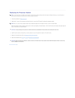
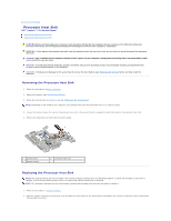
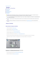
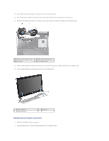
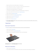
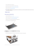
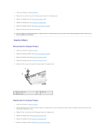
3. Replace the three screws that secure the display assembly to the computer base. 4. Connect the display cable to the connector on the system board, and replace the display cable grounding screw. 5. Route the Mini-Card antenna cables through the routing guides on the palm rest. 6. Thread the Mini-Card antenna cables through the slot in the computer base. 7. Turn the computer over and replace the two screws that secure the display assembly to the computer base. 8. Route and connect the Mini-Card antenna cables (see step 5 in Replacing the Mini-Card). 9. Replace the keyboard (see Replacing the Keyboard). 10. Replace the power button panel (see Replacing the Power Button Panel). 11. Replace the module cover (see Replacing the Module Cover). 12. Replace the optical drive (see Replacing the Optical Drive). 13. Replace the battery (see Replacing the Battery). CAUTION: Before turning on the computer, replace all screws and ensure that no stray screws remain inside the computer. Failure to do so may result in damage to the computer. Display Bezel Removing the Display Bezel CAUTION: The display bezel is extremely fragile. Be careful when removing it to prevent damaging the bezel. 1. Follow the procedures in Before You Begin. 2. Remove the display assembly (see Removing the Display Assembly). 3. Carefully pull up around the inside edges of the display bezel to remove it from the display assembly. 1 display bezel 2 display assembly Replacing the Display Bezel 1. Follow the procedures in Before You Begin. 2. Ensure the display cable and Mini-Card antenna cables run through the notch on the left hinge to keep the cables clear of the display bezel.
-
 1
1 -
2
-
3
-
4
-
5
-
6
-
7
-
8
-
9
-
10
-
11
-
12
-
13
-
14
-
15
-
 16
16 -
 17
17 -
 18
18 -
 19
19 -
 20
20 -
 21
21 -
 22
22 -
 23
23 -
 24
24 -
 25
25 -
 26
26 -
27
-
28
-
29
-
30
-
31
-
32
-
33
-
34
-
35
-
36
-
37
-
38
-
39
-
40
-
41
-
42
-
43
-
44
-
45
-
46
-
47
-
48
-
49
-
50
-
51
-
52
-
53
-
54
-
55
-
56
-
57
 |
 |
