Dell Inspiron 6000 Service Manual - Page 12
Display Bezel - wireless will not connect
 |
View all Dell Inspiron 6000 manuals
Add to My Manuals
Save this manual to your list of manuals |
Page 12 highlights
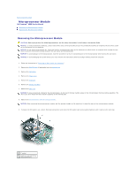
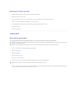
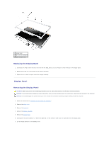
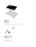
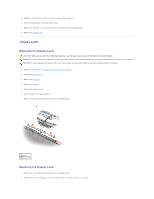
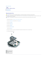
Replacing the Display Assembly 1. Align the display assembly over the screw holes in the base of the computer. 2. Replace the four M2.5 x 5-mm screws. 3. Connect the display cable to the system board connector, and route the display cable in the cable-routing channel. 4. Tighten the screw that connects the grounding wire to the system board. 5. If a wireless Mini PCI card is installed, re-route the antenna cables and connect them to the card. 6. Replace the keyboard. 7. Replace the hinge cover. Display Bezel Removing the Display Bezel CAUTION: Before you perform the following procedures, see the safety instructions in the Product Information Guide. NOTICE: To avoid electrostatic discharge, ground yourself by using a wrist grounding strap or by periodically touching an unpainted metal surface (such as the back panel) on the computer. NOTICE: To avoid damaging the system board, you must remove the main battery before you begin working inside the computer. 1. Follow the instructions in "Preparing to Work Inside the Computer." 2. Remove the hinge cover. 3. Remove the keyboard. 4. Remove the display assembly. 5. Remove the six rubber bumpers. 6. Remove the six M2.5 x 5-mm screws from around the display assembly, and remove the display bezel. NOTICE: Carefully separate the bezel from the display assembly to avoid damage to the bezel. 7. Use your fingers to separate the bezel from the display assembly by lifting the inside edge of the bezel away from the display assembly. Pull the bezel from the top edge toward the center of the panel to open the snaps.
-
 1
1 -
2
-
3
-
4
-
5
-
6
-
 7
7 -
 8
8 -
 9
9 -
 10
10 -
 11
11 -
 12
12 -
 13
13 -
 14
14 -
 15
15 -
 16
16 -
 17
17 -
18
-
19
-
20
-
21
-
22
-
23
-
24
-
25
-
26
-
27
-
28
-
29
-
30
-
31
-
32
-
33
-
34
-
35
-
36
-
37
-
38
-
39
-
40
-
41
-
42
-
43
-
44
-
45
 |
 |
