Dell Inspiron 6000 Service Manual - Page 13
Display Panel
 |
View all Dell Inspiron 6000 manuals
Add to My Manuals
Save this manual to your list of manuals |
Page 13 highlights
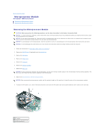
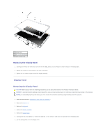
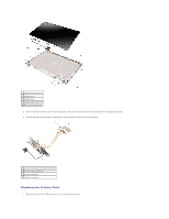
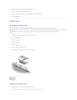
1 display bezel 2 M2.5 x 5-mm screws (6) 3 rubber bumpers (6) Replacing the Display Bezel 1. Starting at the hinge end of the bezel (the end with the DELL label), use your fingers to snap the bezel to the display panel. 2. Replace the six M2.5 x 5-mm screws on the front of the bezel. 3. Replace the six rubber bumpers around the display assembly. Display Panel Removing the Display Panel CAUTION: Before you perform the following procedures, see the safety instructions in the Product Information Guide. NOTICE: To avoid electrostatic discharge, ground yourself by using a wrist grounding strap or by touching an unpainted metal surface on the computer. NOTICE: To avoid damaging the system board, you must remove the main battery before you begin working inside the computer. 1. Follow the instructions in "Preparing to Work Inside the Computer." 2. Remove the hinge cover. 3. Remove the keyboard. 4. Remove the display assembly. 5. Remove the display bezel. 6. Starting with the screw labeled "1," remove the eight M2 x 3-mm screws in order (four on each side) from the display panel. 7. Lift the display panel out of the display cover.
-
 1
1 -
2
-
3
-
4
-
5
-
6
-
7
-
 8
8 -
 9
9 -
 10
10 -
 11
11 -
 12
12 -
 13
13 -
 14
14 -
 15
15 -
 16
16 -
 17
17 -
 18
18 -
19
-
20
-
21
-
22
-
23
-
24
-
25
-
26
-
27
-
28
-
29
-
30
-
31
-
32
-
33
-
34
-
35
-
36
-
37
-
38
-
39
-
40
-
41
-
42
-
43
-
44
-
45
 |
 |
