Dell Inspiron N5030 Service Guide - Page 10
Processor Module - skins
 |
View all Dell Inspiron N5030 manuals
Add to My Manuals
Save this manual to your list of manuals |
Page 10 highlights
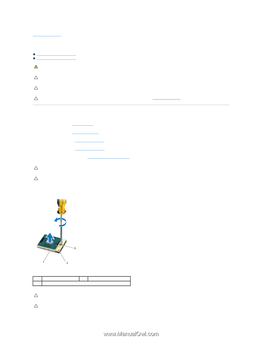
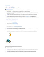
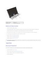
Back to Contents Page Processor Module Dell™ Inspiron™ N5020/M5030/N5030 Service Manual Removing the Processor Module Replacing the Processor Module WARNING: Before working inside your computer, read the safety information that shipped with your computer. For additional safety best practices information, see the Regulatory Compliance Homepage at www.dell.com/regulatory_compliance. CAUTION: Only a certified service technician should perform repairs on your computer. Damage due to servicing that is not authorized by Dell™ is not covered by your warranty. CAUTION: To avoid electrostatic discharge, ground yourself by using a wrist grounding strap or by periodically touching an unpainted metal surface (such as a connector on your computer). CAUTION: To help prevent damage to the system board, remove the main battery (see Removing the Battery) before working inside the computer. Removing the Processor Module 1. Follow the instructions in Before You Begin. 2. Remove the battery (see Removing the Battery). 3. Remove the keyboard (see Removing the Keyboard). 4. Remove the palm rest (see Removing the Palm Rest). 5. Remove the processor heat sink (see Removing the Processor Heat Sink). CAUTION: To prevent intermittent contact between the ZIF-socket cam screw and the processor when removing or replacing the processor, press to apply slight pressure to the center of the processor while turning the cam screw. CAUTION: To avoid damage to the processor, hold the screwdriver so that it is perpendicular to the processor when turning the cam screw. 6. To loosen the ZIF socket, use a small, flat-blade screwdriver and rotate the ZIF-socket cam screw counterclockwise until it comes to the cam stop. 1 ZIF socket 3 ZIF-socket cam screw 2 pin-1 corner CAUTION: To ensure maximum cooling for the processor, do not touch the heat transfer areas on the processor thermal-cooling assembly. The oils in your skin can reduce the heat transfer capability of the thermal pads. CAUTION: When removing the processor module, pull the module straight up. Be careful not to bend the pins on the processor module.
-
 1
1 -
2
-
3
-
4
-
 5
5 -
 6
6 -
 7
7 -
 8
8 -
 9
9 -
 10
10 -
 11
11 -
 12
12 -
 13
13 -
 14
14 -
 15
15 -
16
-
17
-
18
-
19
-
20
-
21
-
22
-
23
-
24
-
25
-
26
-
27
-
28
-
29
-
30
-
31
-
32
-
33
-
34
-
35
-
36
-
37
-
38
-
39
-
40
-
41
 |
 |