Dell Latitude C840 Service Manual - Page 58
Lift the front of the system board and work it out of the back panel.
 |
UPC - 609525176179
View all Dell Latitude C840 manuals
Add to My Manuals
Save this manual to your list of manuals |
Page 58 highlights
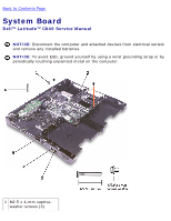
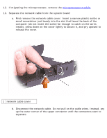
System Board: Dell Latitude C840 Service Manual 1 outer corner of upper connector 2 network cable 14. Remove the three M2.5 x 4-mm captive-washer screws from the system board. 15. Remove the M2.5 x 20-mm screw from the center of the LED board. 16. Lift the front of the system board and work it out of the back panel. If necessary to help release the system board, pull outward on the top of the plastic near the back left corner of the bottom case (see the small arrow at the far left in the following figure). System Board file:///F|/Service%20Manuals/Dell/Latitude/c840/sysboard.htm (4 of 5) [2/28/2004 8:03:45 AM]
-
 1
1 -
2
-
3
-
4
-
5
-
6
-
7
-
8
-
9
-
10
-
11
-
12
-
13
-
14
-
15
-
16
-
17
-
18
-
19
-
20
-
21
-
22
-
23
-
24
-
25
-
26
-
27
-
28
-
29
-
30
-
31
-
32
-
33
-
34
-
35
-
36
-
37
-
38
-
39
-
40
-
41
-
42
-
43
-
44
-
45
-
46
-
47
-
48
-
49
-
50
-
51
-
52
-
 53
53 -
 54
54 -
 55
55 -
 56
56 -
 57
57 -
 58
58 -
 59
59 -
 60
60 -
 61
61 -
 62
62 -
 63
63 -
64
-
65
-
66
-
67
-
68
-
69
-
70
-
71
-
72
-
73
-
74
-
75
-
76
-
77
-
78
-
79
-
80
-
81
 |
 |

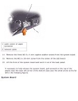
System Board: Dell Latitude C840 Service Manual
1
outer corner of upper
connector
2
network cable
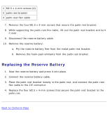
14.
Remove the three M2.5 x 4-mm captive-washer screws from the system board.
15.
Remove the M2.5 x 20-mm screw from the center of the LED board.
16.
Lift the front of the system board and work it out of the back panel.
If necessary to help release the system board, pull outward on the top of the
plastic near the back left corner of the bottom case (see the small arrow at the far
left in the following figure).
System Board
file:///F|/Service%20Manuals/Dell/Latitude/c840/sysboard.htm (4 of 5) [2/28/2004 8:03:45 AM]