Dell Latitude D430 Service Manual - Page 15
Display Assembly - keyboard covers
 |
View all Dell Latitude D430 manuals
Add to My Manuals
Save this manual to your list of manuals |
Page 15 highlights
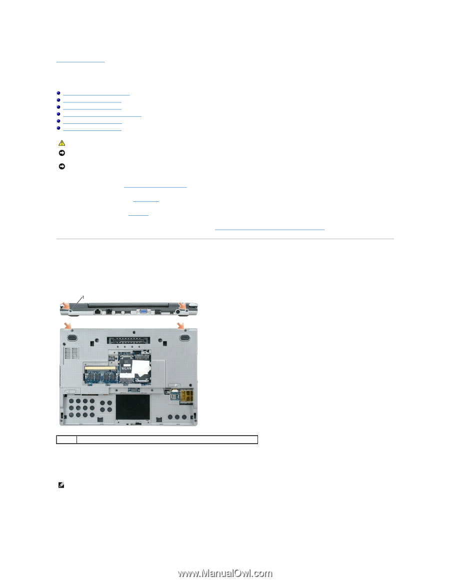
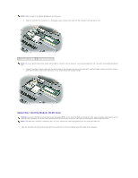
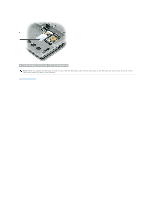
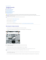
Back to Contents Page Display Assembly Dell™ Latitude™ D430 Removing the Display Assembly Removing the Display Bezel Removing the Display Panel Removing the Display-Panel Brackets Removing the Display Cable Removing the Display Latch CAUTION: Before you begin any of the procedures in this section, follow the safety instructions in the Product Information Guide. NOTICE: To avoid electrostatic discharge, ground yourself by using a wrist grounding strap or by periodically touching an unpainted metal surface (such as the back panel) on the computer. NOTICE: You must remove the display assembly before you remove the palm rest. 1. Follow the instructions in "Before You Begin" on page 7. 2. Remove the hinge cover (see Hinge Cover). 3. Remove the keyboard (see Keyboard). 4. Remove the internal card with Bluetooth® wireless technology (see Internal Card With Bluetooth® Wireless Technology). Removing the Display Assembly 1. Remove the two M2.5 x 5-mm left and right hinge screws from the back of the computer. 2. Turn the computer upside down and remove the two M2.5 x 5-mm screws labeled "D" from the computer base. 1 M2.5 x 5-mm screws (4) 3. Remove the antenna cables from the WLAN and Mobile Broadband Mini- Cards, if applicable. 4. Turn the computer over topside up and open the display approximately 180 degrees so that it lies flat against your work surface. NOTE: Ensure that any plastic sleeves that protect unconnected Mini-Card connectors do not slide off. 5. Carefully dislodge the Mini-Card antenna cables from their routing guides and pull the cables with their connectors through the system board so that they are clear of the computer base. 6. Pull on the display cable pull-tab toward the back of the computer to disconnect the display cable from the display connector on the system board.
-
 1
1 -
2
-
3
-
4
-
5
-
6
-
7
-
8
-
9
-
 10
10 -
 11
11 -
 12
12 -
 13
13 -
 14
14 -
 15
15 -
 16
16 -
 17
17 -
 18
18 -
 19
19 -
 20
20 -
21
-
22
-
23
-
24
-
25
-
26
-
27
-
28
-
29
-
30
-
31
-
32
-
33
-
34
-
35
-
36
-
37
 |
 |