Dell Latitude D430 Service Manual - Page 26
Modem - remove hard drive
 |
View all Dell Latitude D430 manuals
Add to My Manuals
Save this manual to your list of manuals |
Page 26 highlights
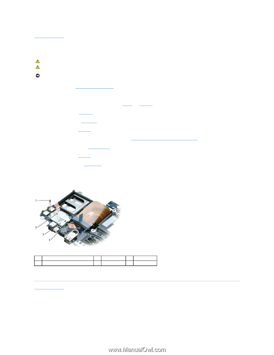
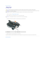
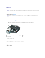
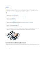
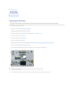
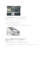
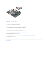
Back to Contents Page Modem Dell™ Latitude™ D430 CAUTION: Before you begin any of the procedures in this section, follow the safety instructions in the Product Information Guide. CAUTION: To prevent static damage to components inside your computer, discharge static electricity from your body before you touch any of your computer's electronic components. You can do so by touching an unpainted metal surface. NOTICE: Handle components and cards by their edges, and avoid touching pins and contacts. 1. Follow the instructions in "Before You Begin" on page 7. 2. Remove any installed PC Cards from the PC Card slot. 3. Remove any installed memory modules or Mini PCI cards (see Memory and Mini-Cards). 4. Remove the hard drive (see Hard Drive). 5. Remove the hinge cover (see Hinge Cover). 6. Remove the keyboard (see Keyboard). 7. Remove the internal card with Bluetooth® wireless technology (see Internal Card With Bluetooth® Wireless Technology). 8. Remove the display assembly (see Display Assembly). 9. Remove the palm rest (see Palm Rest) and lay it aside. 10. Remove the system board (see System Board) and turn it upside down. 11. Remove the modem connector from the bottom of the system board and carefully dislodge the modem cable from the metal clips on the system board. 12. Remove the M2 x 3-mm modem screw and pull up on the modem pull-tab to remove the modem from its socket on the system board. 1 M2 x 3-mm screw 4 modem connector 2 pull-tab 3 modem To replace the modem, ensure that the modem is properly aligned with the socket and that you route the modem cable correctly under the metal clips on the system board. Back to Contents Page
-
 1
1 -
2
-
3
-
4
-
5
-
6
-
7
-
8
-
9
-
10
-
11
-
12
-
13
-
14
-
15
-
16
-
17
-
18
-
19
-
20
-
 21
21 -
 22
22 -
 23
23 -
 24
24 -
 25
25 -
 26
26 -
 27
27 -
 28
28 -
 29
29 -
 30
30 -
 31
31 -
32
-
33
-
34
-
35
-
36
-
37
 |
 |