Dell Latitude E5530 User Manual - Page 45
Removing the Power Connector
 |
View all Dell Latitude E5530 manuals
Add to My Manuals
Save this manual to your list of manuals |
Page 45 highlights
f) palmrest g) thermal module h) processor door i) WLAN card j) hard drive k) optical drive l) keyboard m) keyboard trim n) bottom door o) battery p) SD memory card 4. Follow the procedures in After Working Inside Your Computer. Removing the Power Connector 1. Follow the procedures in Before Working Inside Your Computer. 2. Remove: a) SD memory card b) battery c) bottom door d) keyboard trim e) keyboard f) optical drive g) hard drive h) WLAN card i) processor door j) thermal module k) palmrest l) ExpressCard reader cage m) display assembly n) left support bracket o) system board 3. Remove the power connector cable from the routing channels. 45
-
 1
1 -
2
-
3
-
4
-
5
-
6
-
7
-
8
-
9
-
10
-
11
-
12
-
13
-
14
-
15
-
16
-
17
-
18
-
19
-
20
-
21
-
22
-
23
-
24
-
25
-
26
-
27
-
28
-
29
-
30
-
31
-
32
-
33
-
34
-
35
-
36
-
37
-
38
-
39
-
 40
40 -
 41
41 -
 42
42 -
 43
43 -
 44
44 -
 45
45 -
 46
46 -
 47
47 -
 48
48 -
 49
49 -
 50
50 -
51
-
52
-
53
-
54
-
55
-
56
-
57
-
58
-
59
-
60
-
61
-
62
-
63
-
64
-
65
-
66
-
67
-
68
-
69
-
70
-
71
 |
 |

f)
palmrest
g)
thermal module
h)
processor door
i)
WLAN card
j)
hard drive
k)
optical drive
l)
keyboard
m)
keyboard trim
n)
bottom door
o)
battery
p)
SD memory card
4.
Follow the procedures in
After Working Inside Your Computer
.
Removing the Power Connector
1.
Follow the procedures in
Before Working Inside Your Computer
.
2.
Remove:
a)
SD memory card
b)
battery
c)
bottom door
d)
keyboard trim
e)
keyboard
f)
optical drive
g)
hard drive
h)
WLAN card
i)
processor door
j)
thermal module
k)
palmrest
l)
ExpressCard reader cage
m)
display assembly
n)
left support bracket
o)
system board
3.
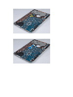
Remove the power connector cable from the routing channels.
45