Dell Latitude L400 Service Manual - Page 13
Display Assembly, Display Assembly Removal
 |
View all Dell Latitude L400 manuals
Add to My Manuals
Save this manual to your list of manuals |
Page 13 highlights
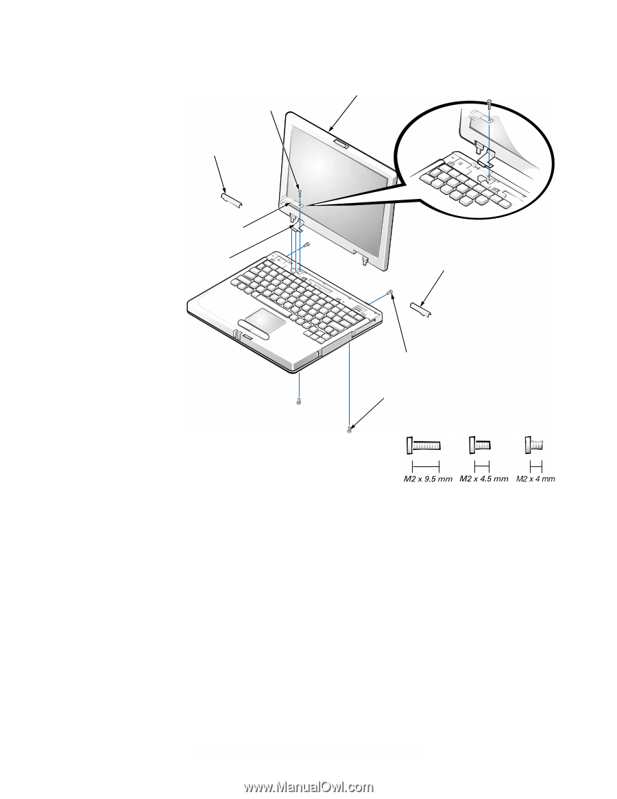
Display Assembly M2 x 9.5-mm screw left hinge cover display assembly LCD flex-cable hold-down clip LCD flex cable right hinge cover M2 x 4-mm screws (2) M2 x 4.5-mm screws (2) Figure 8. Display Assembly Removal NOTICE: To avoid damaging the system board, you must remove the battery before you service the computer. 1. Remove the keyboard bezel. 2. Close the display. 3. Remove the two silver M2 x 4-mm screws at the back of the computer that secure the display assembly to the bottom case (see Figure 8). 4. Turn the computer upside down on a flat work surface. 5. Remove the two M2 x 4.5-mm screws at the bottom of the computer that secure the display assembly to the bottom case (see Figure 8). support.dell.com Dell Latitude L400 Service Manual 9
-
 1
1 -
2
-
3
-
4
-
5
-
6
-
7
-
 8
8 -
 9
9 -
 10
10 -
 11
11 -
 12
12 -
 13
13 -
 14
14 -
 15
15 -
 16
16 -
 17
17 -
 18
18 -
19
-
20
-
21
-
22
-
23
-
24
-
25
-
26
-
27
-
28
-
29
-
30
-
31
-
32
-
33
-
34
-
35
-
36
-
37
-
38
-
39
-
40
 |
 |