Dell Latitude L400 Service Manual - Page 15
Display Assembly Bezel,
 |
View all Dell Latitude L400 manuals
Add to My Manuals
Save this manual to your list of manuals |
Page 15 highlights
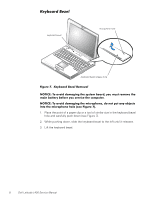
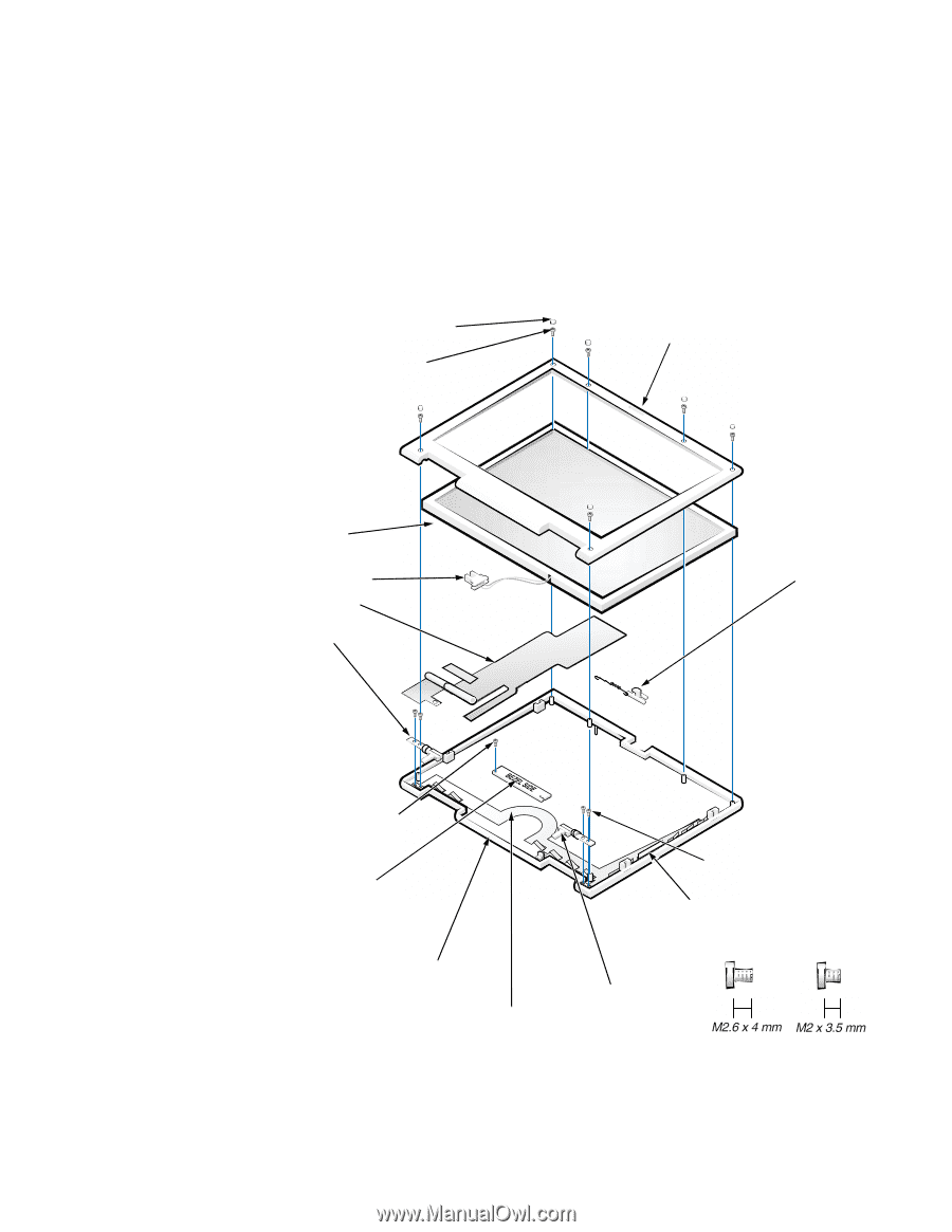
7. Reinstall the two M2 x 4-mm screws in the back of the computer that secure the display assembly to the back of the bottom case. 8. Tighten the two screws that you installed in step 6. 9. Open the display and reinstall the left and right hinge covers. An L is stamped on the bottom of the left hinge cover and an R is stamped on the bottom of the right hinge cover. Display Assembly Bezel l large rubber screw covers (6) M2 x 3.5-mm screws (6) display assembly bezel LCD panel back light plug LCD flex cable left hinge latch M2 x 3.5-mm screw inverter M2.6 x 4-mm screws (4) EMI sponges (2) display-assembly top cover EMI shield right hinge Figure 9. Display Assembly Bezel Removal support.dell.com Dell Latitude L400 Service Manual 11
-
 1
1 -
2
-
3
-
4
-
5
-
6
-
7
-
8
-
9
-
 10
10 -
 11
11 -
 12
12 -
 13
13 -
 14
14 -
 15
15 -
 16
16 -
 17
17 -
 18
18 -
 19
19 -
 20
20 -
21
-
22
-
23
-
24
-
25
-
26
-
27
-
28
-
29
-
30
-
31
-
32
-
33
-
34
-
35
-
36
-
37
-
38
-
39
-
40
 |
 |
support.dell.com
Dell Latitude L400 Service Manual
11
7.
Reinstall the two M2 x 4-mm screws in the back of the computer that
secure the display assembly to the back of the bottom case.
8.
Tighten the two screws that you installed in step 6.
9.
Open the display and reinstall the left and right hinge covers.
An
L
is stamped on the bottom of the left hinge cover and an
R
is stamped
on the bottom of the right hinge cover.
Display Assembly Bezel
l
Figure 9.
Display Assembly Bezel Removal
LCD panel
display-assembly top cover
inverter
display assembly bezel
large rubber screw covers (6)
M2 x 3.5-mm screws (6)
latch
left hinge
right hinge
M2.6 x 4-mm screws (4)
M2 x 3.5-mm screw
back light plug
EMI sponges (2)
LCD flex cable
EMI shield