Dell Latitude L400 Service Manual - Page 30
fan to the bottom assembly., Reinstall the M2 x 8-mm screws with double rubber washers to secure
 |
View all Dell Latitude L400 manuals
Add to My Manuals
Save this manual to your list of manuals |
Page 30 highlights
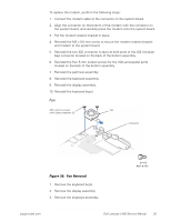
4. Remove the palmrest assembly. 5. Carefully disconnect the fan wire connector from the system board (see Figure 20). The male connector on the fan wire is keyed to fit into the female connector one way only. 6. Remove the two M2 x 8-mm screws with double rubber washers that secure the fan to the bottom assembly (see Figure 20). 7. Remove the fan from the bottom assembly. To replace the fan, perform the following steps: 1. Place the fan in the bottom assembly. NOTE: Make sure that the fan wire is pointing toward the connector on the system board assembly. 2. Reinstall the M2 x 8-mm screws with double rubber washers to secure the fan to the bottom assembly. NOTE: Make sure that the two M2 x 8-mm screws are installed with two rubber washers apiece. 3. Reconnect the fan wire to the connector on the system board assembly. 4. Replace the palmrest assembly. 5. Replace the keyboard assembly. 6. Replace the display assembly. 7. Replace the keyboard bezel. 26 Dell Latitude L400 Service Manual
-
 1
1 -
2
-
3
-
4
-
5
-
6
-
7
-
8
-
9
-
10
-
11
-
12
-
13
-
14
-
15
-
16
-
17
-
18
-
19
-
20
-
21
-
22
-
23
-
24
-
 25
25 -
 26
26 -
 27
27 -
 28
28 -
 29
29 -
 30
30 -
 31
31 -
 32
32 -
 33
33 -
 34
34 -
 35
35 -
36
-
37
-
38
-
39
-
40
 |
 |
