Dell Latitude L400 Service Manual - Page 7
Screw Identification and Tightening, Main Battery Assembly Removal, Screw Identification - service manual
 |
View all Dell Latitude L400 manuals
Add to My Manuals
Save this manual to your list of manuals |
Page 7 highlights
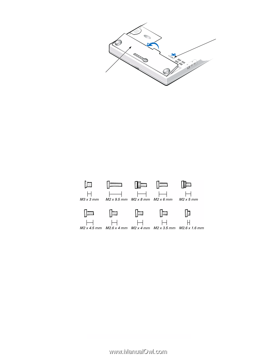
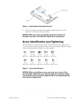
battery latch battery Figure 2. Main Battery Assembly Removal 9. Ground yourself by touching the unpainted metal surface of an I/O connector on the back of the computer. NOTICE: While you work, periodically touch the I/O panel to dissipate any static electricity that might harm components. Screw Identification and Tightening The illustrations in the following removal procedures provide lengths of the correct screws for each procedure. Figure 3 shows examples. Match the actual screw to the illustration to check for correct length. Figure 3. Screw Identification NOTICE: When reinstalling a screw, you must use a screw of the correct length. Otherwise, you could damage the hardware. Make sure that the screw is properly aligned with its corresponding hole, and avoid overtightening. support.dell.com Dell Latitude L400 Service Manual 3
-
 1
1 -
 2
2 -
 3
3 -
 4
4 -
 5
5 -
 6
6 -
 7
7 -
 8
8 -
 9
9 -
 10
10 -
 11
11 -
 12
12 -
13
-
14
-
15
-
16
-
17
-
18
-
19
-
20
-
21
-
22
-
23
-
24
-
25
-
26
-
27
-
28
-
29
-
30
-
31
-
32
-
33
-
34
-
35
-
36
-
37
-
38
-
39
-
40
 |
 |