Dell Latitude L400 Service Manual - Page 17
LCD Panel, LCD Panel Removal
 |
View all Dell Latitude L400 manuals
Add to My Manuals
Save this manual to your list of manuals |
Page 17 highlights
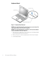
To replace the display-assembly latch, perform the following steps: 1. Carefully place the latch spring over the post on the display-assembly top cover. You may need to use a small flat-blade screwdriver to place the spring over the post. Hold the spring on the post with the screwdriver while performing the next step. 2. Holding the latch, stretch the spring slightly and set the display-assembly latch in place in the display assembly top cover. 3. Reinstall the bezel. LCD Panel LCD panel back light plug M2 x 3.5-mm screws (4) narrow flex cable ZIF connector M2 x 3.5-mm screw EMI shield inverter inverter back light plug wide flex cable narrow flex cable EMI sponges (2) LCD flex cable Figure 11. LCD Panel Removal NOTICE: To avoid damaging the system board, you must remove the main battery before you service the computer. 1. Ground yourself by touching the unpainted metal surface of the I/O panel on the back of the computer. support.dell.com Dell Latitude L400 Service Manual 13
-
 1
1 -
2
-
3
-
4
-
5
-
6
-
7
-
8
-
9
-
10
-
11
-
 12
12 -
 13
13 -
 14
14 -
 15
15 -
 16
16 -
 17
17 -
 18
18 -
 19
19 -
 20
20 -
 21
21 -
 22
22 -
23
-
24
-
25
-
26
-
27
-
28
-
29
-
30
-
31
-
32
-
33
-
34
-
35
-
36
-
37
-
38
-
39
-
40
 |
 |
