Dell OptiPlex GXi Reference and Installation Guide (.pdf) - Page 27
Using the Optional Floor Stand, System User's Guide, Diagnostics and, Troubleshooting Guide - manual
 |
View all Dell OptiPlex GXi manuals
Add to My Manuals
Save this manual to your list of manuals |
Page 27 highlights
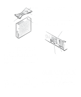
your online System User's Guide and Chapter 2, "Using the System Setup Program." • Advanced power management options that can reduce the energy consumption of your system. For more information, see Chapter 2, "Using the System Setup Program." • The ICU, which tells you how to configure ISA expansion cards manually. After resources have been assigned to these cards, the system BIOS can assign resources to PCI and Plug and Play expansion cards for a conflict-free configuration. For more information, see Chapter 3, "Using the ISA Configuration Utility." • Dell diagnostics for evaluating the computer's com- ponents and devices. For information on using the diagnostics, see the chapter titled "Running the Diskette-Based Diagnostics" in the Diagnostics and Troubleshooting Guide. • Network device drivers for several network operat- ing systems. These drivers are described in Chapter 4, "Using Integrated Devices." • Desktop Management Interface (DMI) support, which enables the management of your computer system's software and hardware. DMI defines the software, interfaces, and data files that enable your system to determine and report information about its components. If your system has a Dell-installed Microsoft Windows®, Windows for Workgroups™, or Windows NT operating system, DMI is already installed on your system's hard-disk drive. You can enable DMI support by double-clicking the DMI icon in the Windows Control Panel (located in the Main program group or folder). For instructions on enabling DMI support or for information about DMI, refer to the DMI online help. You can access the online help by double-clicking the DMI icon in the Control Panel. The DMI online help is also provided in the Dell Accessories program group or folder. • The Dell Inspector utility, which uses DMI support to display detailed information about the hardware and software configuration for your system. The Dell Inspector utility provides you with the information you may need if you call Dell for technical assistance. It also provides you with the information you may need when you install hardware or software in your system. The Dell Inspector utility is located in the Dell Accessories program group or folder. If you ordered Dell-installed software with your system, such as MS-DOS®, Microsoft Windows, or other programs, Dell provides a menu that allows you to make program diskette sets of your Dell-installed software. A program diskette set is an uninstalled version of a software package that you can use to reinstall or reconfigure the software. You can use this same menu to remove diskette image files (individual files that correspond to each diskette in a program diskette set) to reclaim space on the computer's hard-disk drive. For more information on making program diskette sets, see the online help provided in the Dell DiskMaker program, which is available in the Dell Accessories program group or folder. Using the Optional Floor Stand An optional floor stand is available for your system that you can attach to the computer to give it a mini tower (vertical) orientation. Although you can attach (and remove) the floor stand at any time with a minimum of system disruption, it is easiest to attach before you set up your computer and connect the back panel cables. Attach the floor stand as follows: 1. Turn the computer onto its right side, so that the drive bays are at the bottom. 2. Fit the floor stand onto what was the left side of the computer. Position the floor stand as shown in Figure 1-1. Align the large round hole in the floor stand with the securing button on the side of the cover, and align the captive thumbscrew in the stand with the screw hole in the cover. Introduction 1-3
-
 1
1 -
2
-
3
-
4
-
5
-
6
-
7
-
8
-
9
-
10
-
11
-
12
-
13
-
14
-
15
-
16
-
17
-
18
-
19
-
20
-
21
-
 22
22 -
 23
23 -
 24
24 -
 25
25 -
 26
26 -
 27
27 -
 28
28 -
 29
29 -
 30
30 -
 31
31 -
 32
32 -
33
-
34
-
35
-
36
-
37
-
38
-
39
-
40
-
41
-
42
-
43
-
44
-
45
-
46
-
47
-
48
-
49
-
50
-
51
-
52
-
53
-
54
-
55
-
56
-
57
-
58
-
59
-
60
-
61
-
62
-
63
-
64
-
65
-
66
-
67
-
68
-
69
-
70
-
71
-
72
-
73
-
74
-
75
-
76
-
77
-
78
-
79
-
80
-
81
-
82
-
83
-
84
-
85
-
86
-
87
-
88
-
89
-
90
-
91
-
92
-
93
-
94
-
95
-
96
-
97
-
98
-
99
-
100
-
101
-
102
-
103
-
104
-
105
-
106
-
107
-
108
-
109
-
110
-
111
-
112
-
113
-
114
-
115
-
116
-
117
-
118
-
119
-
120
-
121
-
122
-
123
-
124
-
125
-
126
-
127
-
128
-
129
-
130
-
131
-
132
-
133
-
134
 |
 |
