Dell OptiPlex GXi Reference and Installation Guide (.pdf) - Page 28
Security Cable Slot and Padlock Ring, Energy Star Compliance,
 |
View all Dell OptiPlex GXi manuals
Add to My Manuals
Save this manual to your list of manuals |
Page 28 highlights
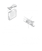
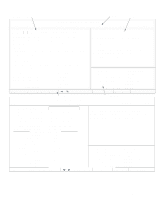
locator pin (on underside of floor stand) captive screw locator hole securing button slot on the back of your computer, and lock the device with the key provided. Complete instructions for installing this kind of antitheft device are usually included with the device. NOTE: Antitheft devices are of differing designs. Before purchasing such a device, make sure it will work with the cable slot on your computer. The padlock ring allows you to secure the computer cover to the chassis to prevent unauthorized access to the inside of the computer. To use the padlock ring, insert a commercially available padlock through the ring and then lock the padlock. padlock ring Figure 1-1. Attaching the Optional Floor Stand As you lower the stand into place, make sure the locator pin (see Figure 1-1) heads into the corner hole of the hole pattern as shown. When the stand is in place, tighten the thumbscrew. 3. Rotate the computer so that the floor stand is at the bottom and the drives are at the top. To remove the floor stand, turn the computer over so the floor stand is at the top, loosen the screw and lift the floor stand away, and place the computer in a horizontal position. Security Cable Slot and Padlock Ring To the right of the fan vent on the back of the computer are a security cable slot and padlock ring (see Figure 1-2) for attaching a commercially available antitheft device. Antitheft cable devices for personal computers usually include a segment of galvanized cable with an attached locking device and key. To prevent unauthorized removal of your computer, loop the cable around an immovable object, insert the locking device into the security cable fan vent security cable slot Figure 1-2. Security Cable Slot and Padlock Ring Energy Star Compliance Certain configurations of Dell computer systems comply with the requirements set forth by the Environmental Protection Agency (EPA) for energy-efficient computers. If the front panel of your computer bears the Energy Star Emblem (see Figure 1-3), your original configuration complied with these requirements and all Energy Star power management features of the computer are enabled. To disable or change the operation of these features, you must change the setting for the POWER MANAGEMENT category in the System Setup program. For instructions, see Chapter 2, "Using the System Setup Program." 1-4 Dell OptiPlex GXi Low-Profile Systems Reference and Installation Guide
-
 1
1 -
2
-
3
-
4
-
5
-
6
-
7
-
8
-
9
-
10
-
11
-
12
-
13
-
14
-
15
-
16
-
17
-
18
-
19
-
20
-
21
-
22
-
 23
23 -
 24
24 -
 25
25 -
 26
26 -
 27
27 -
 28
28 -
 29
29 -
 30
30 -
 31
31 -
 32
32 -
 33
33 -
34
-
35
-
36
-
37
-
38
-
39
-
40
-
41
-
42
-
43
-
44
-
45
-
46
-
47
-
48
-
49
-
50
-
51
-
52
-
53
-
54
-
55
-
56
-
57
-
58
-
59
-
60
-
61
-
62
-
63
-
64
-
65
-
66
-
67
-
68
-
69
-
70
-
71
-
72
-
73
-
74
-
75
-
76
-
77
-
78
-
79
-
80
-
81
-
82
-
83
-
84
-
85
-
86
-
87
-
88
-
89
-
90
-
91
-
92
-
93
-
94
-
95
-
96
-
97
-
98
-
99
-
100
-
101
-
102
-
103
-
104
-
105
-
106
-
107
-
108
-
109
-
110
-
111
-
112
-
113
-
114
-
115
-
116
-
117
-
118
-
119
-
120
-
121
-
122
-
123
-
124
-
125
-
126
-
127
-
128
-
129
-
130
-
131
-
132
-
133
-
134
 |
 |
