Dell PowerConnect 2708 User's Guide - Page 16
PowerConnect 2708 Back Panel, or not. A Managed Mode push-button - configuration
 |
View all Dell PowerConnect 2708 manuals
Add to My Manuals
Save this manual to your list of manuals |
Page 16 highlights
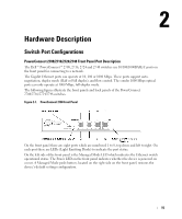
Figure 2-2. PowerConnect 2708 Back Panel Figure 2-3. PowerConnect 2716 Front Panel On the front panel, there are 16 ports, which are numbered 1 to 16, top down and left to right. On each port there are LEDs to indicate the port status. On the left side of the front panel is the Managed Mode LED which indicates the Ethernet switch operational status. The Power LED on the front panel indicates whether the device is powered on or not. A Managed Mode push-button, located on the right side on the front panel, restores the device's default settings configuration. Figure 2-4. PowerConnect 2716 Back Panel 16
-
 1
1 -
2
-
3
-
4
-
5
-
6
-
7
-
8
-
9
-
10
-
 11
11 -
 12
12 -
 13
13 -
 14
14 -
 15
15 -
 16
16 -
 17
17 -
 18
18 -
 19
19 -
 20
20 -
 21
21 -
22
-
23
-
24
-
25
-
26
-
27
-
28
-
29
-
30
-
31
-
32
-
33
-
34
-
35
-
36
-
37
-
38
-
39
-
40
-
41
-
42
-
43
-
44
-
45
-
46
-
47
-
48
-
49
-
50
-
51
-
52
-
53
-
54
-
55
-
56
-
57
-
58
-
59
-
60
-
61
-
62
-
63
-
64
-
65
-
66
-
67
-
68
-
69
-
70
-
71
-
72
-
73
-
74
-
75
-
76
-
77
-
78
-
79
-
80
-
81
-
82
-
83
-
84
 |
 |
16
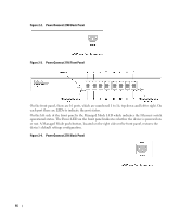
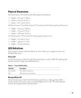
Figure 2-2.
PowerConnect 2708 Back Panel
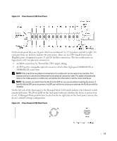
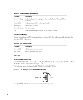
Figure 2-3.
PowerConnect 2716 Front Panel
On the front panel, there are 16 ports, which are numbered 1 to 16, top down and left to right. On
each port there are LEDs to indicate the port status.
On the left side of the front panel is the Managed Mode LED which indicates the Ethernet switch
operational status. The Power LED on the front panel indicates whether the device is powered on
or not. A Managed Mode push-button, located on the right side on the front panel, restores the
device’s default settings configuration.
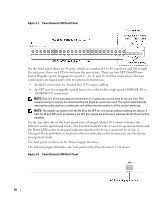
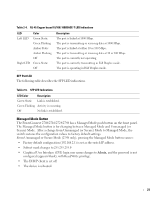
Figure 2-4.
PowerConnect 2716 Back Panel