Dell PowerConnect J-EX4200 Hardware Guide - Page 110
Attaching the Mounting Bracket Along the Front of the Switch
 |
View all Dell PowerConnect J-EX4200 manuals
Add to My Manuals
Save this manual to your list of manuals |
Page 110 highlights
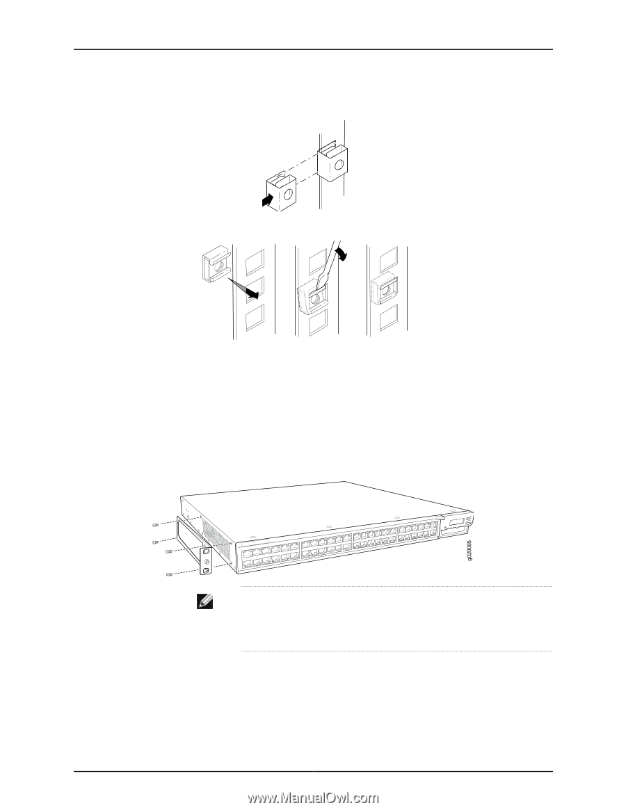
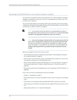
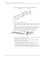
g040637 g040639 Dell PowerConnect J-Series J-EX4200 Ethernet Switch Hardware Guide Figure 27: Installing a Round-Hole Cage Nut (Clip Nut) Figure 28: Installing a Square-Hole Cage Nut b. To ensure that the switch chassis is level after installation, verify that the cage nuts on one side of the rack are aligned with the cage nuts on the other side. 2. Place the switch on a flat, stable surface. 3. Align the mounting brackets along the front, rear, or center of the side panels of the switch chassis depending on how you want to mount the switch. For example, if you want to center-mount the switch, align the brackets along the centers of the side panel. See Figure 29 on page 94. Figure 29: Attaching the Mounting Bracket Along the Front of the Switch NOTE: To mount the switch in a recessed position, use the 2-in.-recess front mount brackets from the separately orderable four-post rack-mount kit. 4. Align the bottom holes in the mounting brackets with holes on the side panels of the switch chassis. 5. Insert mounting screws into the aligned holes. Tighten the screws. 6. Ensure that the other holes in the mounting brackets are aligned with the holes in the side panels. Insert a screw in each hole and tighten the screws. 94
-
 1
1 -
2
-
3
-
4
-
5
-
6
-
7
-
8
-
9
-
10
-
11
-
12
-
13
-
14
-
15
-
16
-
17
-
18
-
19
-
20
-
21
-
22
-
23
-
24
-
25
-
26
-
27
-
28
-
29
-
30
-
31
-
32
-
33
-
34
-
35
-
36
-
37
-
38
-
39
-
40
-
41
-
42
-
43
-
44
-
45
-
46
-
47
-
48
-
49
-
50
-
51
-
52
-
53
-
54
-
55
-
56
-
57
-
58
-
59
-
60
-
61
-
62
-
63
-
64
-
65
-
66
-
67
-
68
-
69
-
70
-
71
-
72
-
73
-
74
-
75
-
76
-
77
-
78
-
79
-
80
-
81
-
82
-
83
-
84
-
85
-
86
-
87
-
88
-
89
-
90
-
91
-
92
-
93
-
94
-
95
-
96
-
97
-
98
-
99
-
100
-
101
-
102
-
103
-
104
-
 105
105 -
 106
106 -
 107
107 -
 108
108 -
 109
109 -
 110
110 -
 111
111 -
 112
112 -
 113
113 -
 114
114 -
 115
115 -
116
-
117
-
118
-
119
-
120
-
121
-
122
-
123
-
124
-
125
-
126
-
127
-
128
-
129
-
130
-
131
-
132
-
133
-
134
-
135
-
136
-
137
-
138
-
139
-
140
-
141
-
142
-
143
-
144
-
145
-
146
-
147
-
148
-
149
-
150
-
151
-
152
-
153
-
154
-
155
-
156
-
157
-
158
-
159
-
160
-
161
-
162
-
163
-
164
-
165
-
166
-
167
-
168
-
169
-
170
-
171
-
172
-
173
-
174
-
175
-
176
-
177
-
178
-
179
-
180
-
181
-
182
-
183
-
184
-
185
-
186
-
187
-
188
-
189
-
190
-
191
-
192
-
193
-
194
-
195
-
196
-
197
-
198
-
199
-
200
-
201
-
202
-
203
-
204
-
205
-
206
-
207
-
208
-
209
-
210
-
211
-
212
-
213
-
214
-
215
-
216
-
217
-
218
-
219
-
220
-
221
-
222
-
223
-
224
-
225
-
226
-
227
-
228
-
229
-
230
-
231
-
232
-
233
-
234
-
235
-
236
-
237
-
238
 |
 |