Dell PowerConnect W-650 Installation Guide - Page 14
Dell PowerConnect W-650 Manual
 |
View all Dell PowerConnect W-650 manuals
Add to My Manuals
Save this manual to your list of manuals |
Page 14 highlights
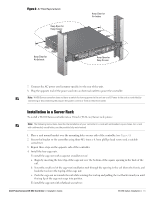
Figure 6 Rack Mount Brackets Rack Mount Bracket (2x) 6-32 x 1/4" Phillips Flat Head Screws (6x, 2x per bracket) 4. Mount the controller within your organization's rack system using four 12-24 x 5/8" phillips head screws and suitable screwdriver (see Figure 7). Figure 7 Rack Mount Installation Standard 19-inch Rack System 12-24 x 5/8" Phillips Flat Head Screws (4x, 2x per bracket) 5. Leave a minimum of four inches (10cm) of space on the left and right side of the unit for proper air flow and ventilation (see Figure 8). 6. Leave additional space in front and back of the unit to access power cords, network cables, and LED status indicators (see Figure 8). 14 | W-650 Series Installation Dell PowerConnect W-650 Controller | Installation Guide
-
 1
1 -
2
-
3
-
4
-
5
-
6
-
7
-
8
-
 9
9 -
 10
10 -
 11
11 -
 12
12 -
 13
13 -
 14
14 -
 15
15 -
 16
16 -
 17
17 -
 18
18 -
 19
19 -
20
 |
 |
14
|
W-650 Series Installation
Dell PowerConnect W-650 Controller
|
Installation Guide
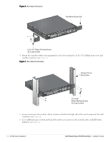
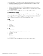
Figure 6
Rack Mount Brackets
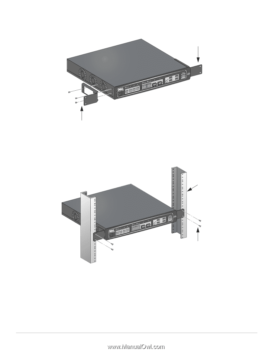
4.
Mount the controller within your organization’s rack system using four 12-24 x 5/8” phillips head screws and
suitable screwdriver (see
Figure 7
).
Figure 7
Rack Mount Installation
5.
Leave a minimum of four inches (10cm) of space on the left and right side of the unit for proper air flow and
ventilation (see
Figure 8
).
6.
Leave additional space in front and back of the unit to access power cords, network cables, and LED status
indicators (see
Figure 8
).
6-32 x 1/4” Phillips Flat Head Screws
(6x, 2x per bracket)
Rack Mount Bracket (2x)
12-24 x 5/8”
Phillips Flat Head Screws
(4x, 2x per bracket)
Standard 19-inch
Rack System