Dell PowerConnect W-650 Installation Guide - Page 15
Installation in a Server Rack
 |
View all Dell PowerConnect W-650 manuals
Add to My Manuals
Save this manual to your list of manuals |
Page 15 highlights
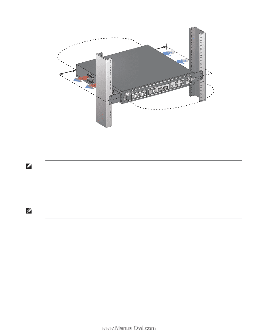
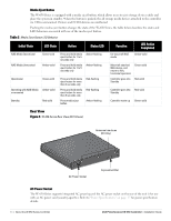
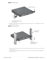
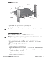
Figure 8 Air Flow Requirements Keep Open for Easy Access Keep Clear for Air Intake Keep Clear for Air Exhaust Keep Open for Easy Access 7. Connect the AC power cord (country-specific) to the rear of the unit. 8. Plug the opposite end of the power cord into an electrical outlet to power the controller. Note: W-650 Series controller does not have a switch for turning power to the unit on or off. Power to the unit is controlled by connecting or disconnecting the plug on the power cord to or from an electrical outlet. Installation in a Server Rack To install a W-650 Series controller into a 19-inch (48.26 cm) Server rack system: Note: The following instructions describe the installation of your controller in a rack with unthreaded, square holes. For a rack with unthreaded, round holes, use the provided clip nuts instead. 1. Place a rack mount bracket over the mounting holes on one side of the controller (see Figure 6). 2. Secure the bracket to the controller using three M3, 6mm x 0.5mm phillips head screws and a suitable screwdriver. 3. Repeat these steps on the opposite side of the controller. 4. Install the four cage nuts. To install the cage nut with a cage-nut installation tool: a. Begin by inserting the lower lip of the cage nut over the bottom of the square opening in the back of the rail. b. Insert the small end of the cage-nut installation tool through the opening in the rail (from the front), and hook the tool over the top lip of the cage nut. c. Push the cage nut in towards the rail while rotating the tool up and pulling the tool back toward you until the top lip of the cage nut snaps into position. To install the cage nut with a flathead screwdriver: Dell PowerConnect W-650 Controller | Installation Guide W-650 Series Installation | 15
-
 1
1 -
2
-
3
-
4
-
5
-
6
-
7
-
8
-
9
-
 10
10 -
 11
11 -
 12
12 -
 13
13 -
 14
14 -
 15
15 -
 16
16 -
 17
17 -
 18
18 -
 19
19 -
 20
20
 |
 |