Dell PowerConnect W-AP134 Installation Guide - Page 2
Device Overview - w ap 134
 |
View all Dell PowerConnect W-AP134 manuals
Add to My Manuals
Save this manual to your list of manuals |
Page 2 highlights
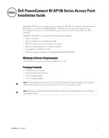
Device Overview Figure 1 W-AP130 Series Access Points (W-AP134 Shown) LED Status Indicators 134 AP-134_003 Antenna Connectors (W-AP134 Only) LEDs The W-AP130 Series access point is equipped with five LEDs that indicate the status of various components of the device. PWR: Indicates the whether or not the W-AP130 Series is powered on and its status. ENET 0: Indicates the status and activity of Ethernet port 0 ENET 1: Indicates the status and activity of Ethernet port 1 11b/g/n: Indicates the status of the 2.4 GHz radio 11a/n: Indicates the status of the 5.0 GHz radio For more information about the LEDs and their behavior, see Table 3 on page 9. External Antenna Connectors The W-AP134 is designed for use with external antennas. The W-AP135 is equipped with internal antennas. 2 Dell PowerConnect W-AP130 Series Access Point | Installation Guide
-
 1
1 -
 2
2 -
 3
3 -
 4
4 -
 5
5 -
 6
6 -
 7
7 -
 8
8 -
9
-
10
-
11
-
12
-
13
-
14
-
15
-
16
 |
 |
