Dell PowerEdge 2450 SCSI Backplane Daughter Card (.pdf) - Page 4
Hard-Disk Drive Configuration, Installing a Fifth SCSI Hard-Disk Drive - power supply
 |
View all Dell PowerEdge 2450 manuals
Add to My Manuals
Save this manual to your list of manuals |
Page 4 highlights
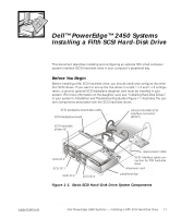
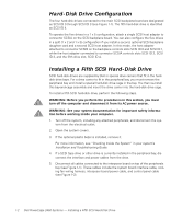
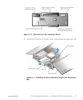
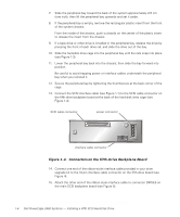
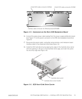
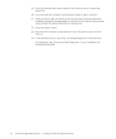
Hard-Disk Drive Configuration The four hard-disk drives connected to the main SCSI backplane board are designated as SCSI ID 0 through SCSI ID 3 (see Figure 1-1). The fifth hard-disk drive is identified as SCSI ID 4. To operate the five drives in a 1 x 5 configuration, attach a single SCSI host adapter to connector SCSIA on the SCSI backplane board. You can also configure the five drives in a split (1 x 2 and 1 x 3) configuration if you install a second, optional SCSI backplane daughter card and a second SCSI host adapter. In this mode, the host adapter attached to connector SCSIB on the backplane controls slots SCSI ID 0 and SCSI ID 1, while the host adapter connected to connector SCSIA controls slots SCSI ID 2, SCSI ID 3, and the fifth drive slot, SCSI ID 4. Installing a Fifth SCSI Hard-Disk Drive SCSI hard-disk drives are supplied by Dell in special drive carriers that fit in the harddisk drive bays. For a drive carrier to fit in the peripheral bay, you must remove the peripheral bay and install a special hard-disk drive cage in the bay. You then re-install this bay-and-cage assembly and insert the drive carrier into the hard-disk drive cage. To install a fifth SCSI hard-disk drive, perform the following steps. WARNING: Before you perform the procedures in this section, you must turn off the computer and disconnect it from its AC power source. WARNING: See your system documentation for important safety information before working inside your computer. 1. Turn off the system, including any attached peripherals, and disconnect the sys- tem from the electrical outlet. 2. Open the system covers. 3. If the optional plastic bezel is installed, remove it. For more information, see "Checking Inside the System" in your system's Installation and Troubleshooting Guide. 4. If a SCSI tape drive or other drive is currently installed in the peripheral bay, disconnect the interface and power cables from the drive. 5. Disconnect all cables connected to the interposer board on top of the peripherals bay (see Figure 1-1). These cables include the system board interface cable, cooling fan wiring harness, interposer board power cable, and control panel cable (see Figure 1-2). 1-2 Dell PowerEdge 2450 Systems - Installing a Fifth SCSI Hard-Disk Drive
-
 1
1 -
 2
2 -
 3
3 -
 4
4 -
 5
5 -
 6
6 -
 7
7 -
 8
8 -
 9
9 -
 10
10 -
11
-
12
-
13
-
14
-
15
-
16
-
17
-
18
-
19
-
20
-
21
-
22
-
23
-
24
-
25
-
26
-
27
-
28
-
29
-
30
-
31
-
32
 |
 |