Dell PowerEdge 2450 SCSI Backplane Daughter Card (.pdf) - Page 6
Connectors on the Fifth-Drive Backplane Board, Dell PowerEdge 2450 Systems - hard drive
 |
View all Dell PowerEdge 2450 manuals
Add to My Manuals
Save this manual to your list of manuals |
Page 6 highlights
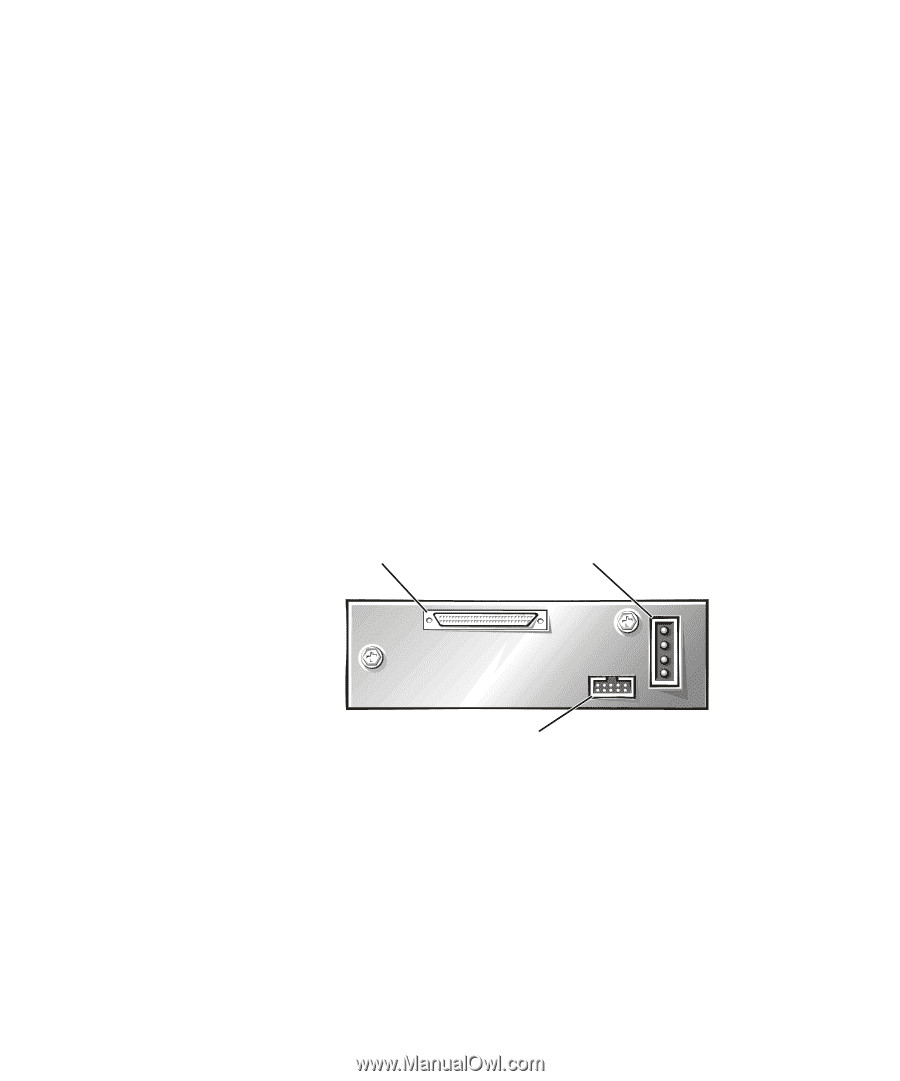
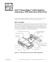
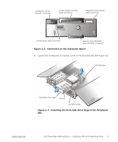
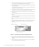
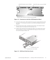
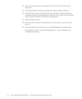
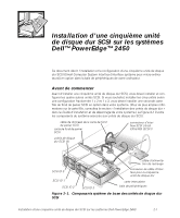
7. Slide the peripheral bay toward the back of the system approximately 2.5 cm (one inch); then lift the peripheral bay upwards and set it aside. 8. If the peripheral bay is empty, remove the rectangular plastic insert from the front of the system chassis. From the inside of the chassis, push outwards on the center of the plastic insert to release the insert from the chassis. 9. If a tape drive or other drive is installed in the peripheral bay, release the drive by pressing the front of each drive rail, and slide the drive out of the bay. 10. Slide the hard-disk drive cage into the peripheral bay until the rails snap into place (see Figure 1-3). 11. Lower the peripheral bay back into the chassis; then slide the bay forward into position. Be careful to avoid trapping power or interface cables underneath the peripheral bay when you reinstall it. 12. Secure the peripheral bay by tightening the thumbscrew at the back corner of the cage. 13. Connect the SCSI interface cable (see Figure 1-1) to the SCSI cable connector on the fifth-drive backplane board at the back of the hard-disk drive cage (see Figure 1-4). SCSI cable connector power connector interface cable connector Figure 1-4. Connectors on the Fifth-Drive Backplane Board 14. Connect one end of the ribbon-style interface cable provided in your drive upgrade kit to the 10-pin interface cable connector on the fifth-drive board (see Figure 4). 15. Attach the other end of the ribbon-style interface cable to connector DRIVE5 on the main SCSI backplane board (see Figure 5). 1-4 Dell PowerEdge 2450 Systems - Installing a Fifth SCSI Hard-Disk Drive
-
 1
1 -
 2
2 -
 3
3 -
 4
4 -
 5
5 -
 6
6 -
 7
7 -
 8
8 -
 9
9 -
 10
10 -
 11
11 -
 12
12 -
13
-
14
-
15
-
16
-
17
-
18
-
19
-
20
-
21
-
22
-
23
-
24
-
25
-
26
-
27
-
28
-
29
-
30
-
31
-
32
 |
 |