Dell PowerEdge 2850 Updating Your NIC Teaming Drivers (.pdf) - Page 3
Removing and Replacing the System Board and Riser Board In A Dell™ PowerEdge™ 1850 System - pci e riser board
 |
View all Dell PowerEdge 2850 manuals
Add to My Manuals
Save this manual to your list of manuals |
Page 3 highlights
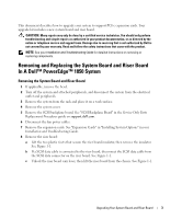
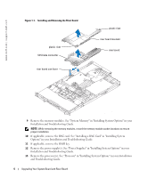
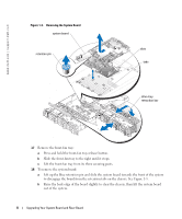
This document describes how to upgrade your system to support PCI-e expansion cards. Your upgrade kit includes a new system board and riser board. CAUTION: Many repairs may only be done by a certified service technician. You should only perform troubleshooting and simple repairs as authorized in your product documentation, or as directed by the online or telephone service and support team. Damage due to servicing that is not authorized by Dell is not covered by your warranty. Read and follow the safety instructions that came with the product. NOTE: See your Installation and Troubleshooting Guide for detailed instructions on removing or replacing components. Removing and Replacing the System Board and Riser Board In A Dell™ PowerEdge™ 1850 System Removing the System Board and Riser Board 1 If applicable, remove the bezel. 2 Turn off the system and attached peripherals, and disconnect the system from the electrical outlet and peripherals. 3 Remove the system from the rack and place it on a work surface. 4 Remove the system cover. 5 Remove the SCSI backplane board. See "SCSI Backplane Board" in the Service-Only Parts Replacement Procedures guide on support.dell.com. 6 Disconnect the fan power cables. 7 Remove the expansion cards. See "Expansion Cards" in "Installing System Options" in your Installation and Troubleshooting Guide. 8 Remove the riser board: a Lift the two plastic rivets that secure the riser board insulator, then remove the insulator. See Figure 1-1. b If a SCSI data cable is connected to the riser board, disconnect the SCSI data cable from the SCSI data connector on the riser board. See Figure 1-1. c Unlock the riser board cam lever, then lift the riser board from the chassis. See Figure 1-1. Upgrading Your System Board and Riser Board 3
-
 1
1 -
 2
2 -
 3
3 -
 4
4 -
 5
5 -
 6
6 -
 7
7 -
 8
8 -
 9
9 -
10
-
11
-
12
-
13
-
14
-
15
-
16
-
17
-
18
-
19
-
20
 |
 |