Dell PowerEdge 2850 Updating Your NIC Teaming Drivers (.pdf) - Page 5
Installing the New System Board and Riser Board - memory slots
 |
View all Dell PowerEdge 2850 manuals
Add to My Manuals
Save this manual to your list of manuals |
Page 5 highlights
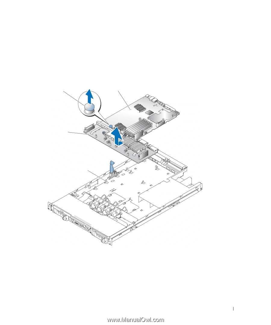
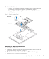
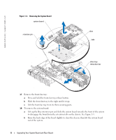
14 To remove the system board: a Lift up the blue retention pin and slide the system board towards the front of the system to disengage the board from the retention tabs on the chassis. See Figure 1-2. b Raise the back edge of the board slightly to clear the chassis, then lift the system board out of the system. Figure 1-2. Removing the System Board retention pin slots system board tabs Installing the New System Board and Riser Board 1 Unpack the new system board. 2 Carefully lower the system board into the chassis until the tabs on the chassis fit through the corresponding slots in the system board. See Figure 1-2. 3 Slide the system board towards the back of the chassis until the retention pin engages. 4 Replace the memory modules in their original locations. Upgrading Your System Board and Riser Board 5
-
 1
1 -
 2
2 -
 3
3 -
 4
4 -
 5
5 -
 6
6 -
 7
7 -
 8
8 -
 9
9 -
 10
10 -
 11
11 -
12
-
13
-
14
-
15
-
16
-
17
-
18
-
19
-
20
 |
 |