Dell PowerEdge 6600 Memory Installation Guidelines (.pdf) - Page 5
Remove the heat sink see
 |
View all Dell PowerEdge 6600 manuals
Add to My Manuals
Save this manual to your list of manuals |
Page 5 highlights
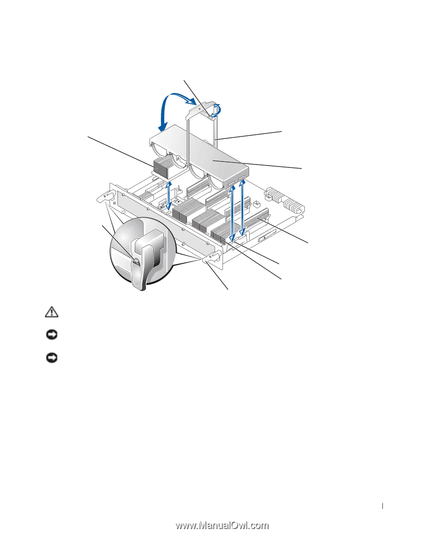
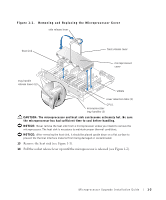
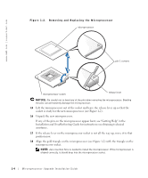
Figure 1-1. Removing and Replacing the Microprocessor Cover side release lever heat sink front release lever microprocessor cover tray handle release levers (2) VRM1 cover retention tabs (2) CPU1 microprocessor tray handles (2) CAUTION: The microprocessor and heat sink can become extremely hot. Be sure the microprocessor has had sufficient time to cool before handling. NOTICE: Never remove the heat sink from a microprocessor unless you intend to remove the microprocessor. The heat sink is necessary to maintain proper thermal conditions. NOTICE: After removing the heat sink, it should be placed upside down on a flat surface to prevent the thermal interface material from being damaged or contaminated. 13 Remove the heat sink (see Figure 1-1). 14 Pull the socket release lever up until the microprocessor is released (see Figure 1-2). Microprocessor Upgrade Installation Guide 1-3
-
 1
1 -
 2
2 -
 3
3 -
 4
4 -
 5
5 -
 6
6 -
 7
7 -
 8
8 -
 9
9 -
 10
10 -
 11
11 -
12
-
13
-
14
-
15
-
16
-
17
-
18
-
19
-
20
-
21
-
22
-
23
-
24
-
25
-
26
-
27
-
28
-
29
-
30
-
31
-
32
-
33
-
34
-
35
-
36
-
37
-
38
-
39
-
40
-
41
-
42
-
43
-
44
-
45
-
46
-
47
-
48
-
49
-
50
-
51
-
52
-
53
-
54
-
55
-
56
-
57
-
58
-
59
-
60
-
61
-
62
-
63
-
64
-
65
-
66
 |
 |