Dell PowerEdge 6600 Memory Installation Guidelines (.pdf) - Page 6
Installation and Troubleshooting Guide, for instructions on obtaining technical
 |
View all Dell PowerEdge 6600 manuals
Add to My Manuals
Save this manual to your list of manuals |
Page 6 highlights
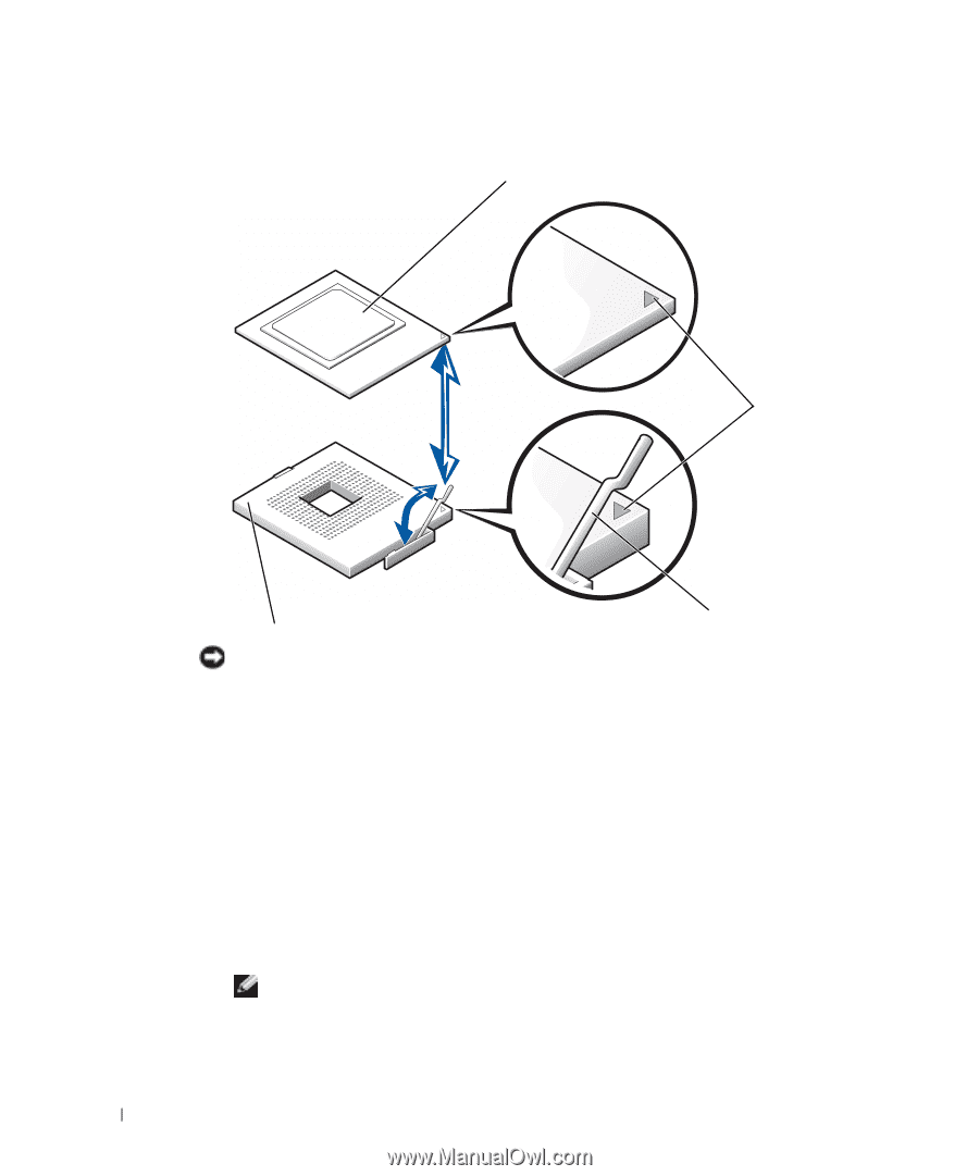
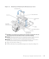
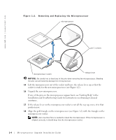
www.dell.com | support.dell.com Figure 1-2. Removing and Replacing the Microprocessor microprocessor pin-1 corners microprocessor socket release lever NOTICE: Be careful not to bend any of the pins when removing the microprocessor. Bending the pins can permanently damage the microprocessor. 15 Lift the microprocessor out of the socket and leave the release lever up so that the socket is ready for the new microprocessor (see Figure 1-2). 16 Unpack the new microprocessor. If any of the pins on the microprocessor appear bent, see "Getting Help" in the Installation and Troubleshooting Guide for instructions on obtaining technical assistance. 17 If the release lever on the microprocessor socket is not all the way up, move it to that position now. 18 Align the gold triangle on the microprocessor (see Figure 1-2) with the triangle on the microprocessor socket. NOTE: Zero insertion force is needed to install the microprocessor. If the microprocessor is aligned correctly, it should drop into the microprocessor socket. 1-4 Mircroprocessor Upgrade Installation Guide
-
 1
1 -
 2
2 -
 3
3 -
 4
4 -
 5
5 -
 6
6 -
 7
7 -
 8
8 -
 9
9 -
 10
10 -
 11
11 -
 12
12 -
13
-
14
-
15
-
16
-
17
-
18
-
19
-
20
-
21
-
22
-
23
-
24
-
25
-
26
-
27
-
28
-
29
-
30
-
31
-
32
-
33
-
34
-
35
-
36
-
37
-
38
-
39
-
40
-
41
-
42
-
43
-
44
-
45
-
46
-
47
-
48
-
49
-
50
-
51
-
52
-
53
-
54
-
55
-
56
-
57
-
58
-
59
-
60
-
61
-
62
-
63
-
64
-
65
-
66
 |
 |